Three-dimensional digital imaging method based on generalized S transformation

A technology of three-dimensional digital and imaging methods, which is applied in the fields of electrical digital data processing, image analysis, image data processing, etc., and can solve the problems of poor adaptability of objects, inability to accurately locate fundamental frequency components, and low phase resolution accuracy.

Active Publication Date: 2015-03-25
SHENZHEN UNIV
View PDF4 Cites 25 Cited by
  • Summary
  • Abstract
  • Description
  • Claims
  • Application Information

AI Technical Summary

Problems solved by technology

Although the shape of the window in the S-transform can change with the frequency and has good time-frequency resolution, the window size is always determined by the real-time frequency of the signal and cannot be changed with the change of the frequency change rate, which makes

Method used


Image

  • Three-dimensional digital imaging method based on generalized S transformation
  • Three-dimensional digital imaging method based on generalized S transformation
  • Three-dimensional digital imaging method based on generalized S transformation

Examples


Embodiment 1

[0088] This embodiment describes the three-dimensional digital imaging device matched with the method of the present invention.

[0089] The three-dimensional digital imaging device matched with the method of the present invention mainly includes a digital projection lighting transmitter, an image sensing receiver and an image processor. Among them, the digital projection lighting transmitter can be a digital liquid crystal projection device (LCD projector), a digital micromirror projection device (DMD projector) or a silicon substrate liquid crystal projection device (LCOS projector), which can be easily generated by a computer image processing system. Grayscale fringe pattern and write to digital projection device. The image sensing receiver includes an optical imaging lens and a photodetector. The optical imaging lens can be an imaging lens or lens group with a fixed focal length or a variable focal length, a binary optical imaging system, a diffraction element imaging syst...

Embodiment 2

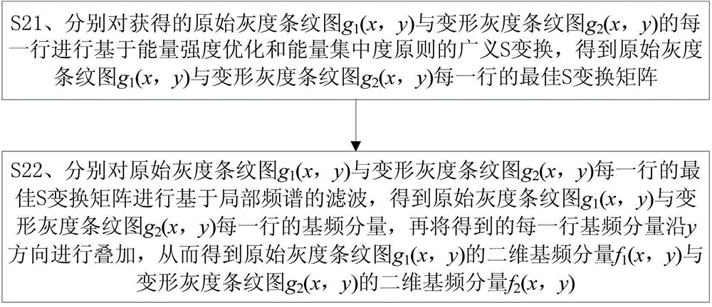
[0092] This embodiment illustrates the process of optimizing the energy intensity of a series of S-transform matrices obtained by using the generalized S-transform for each row of the gray-scale fringe image in the present invention.

[0093] The process of energy intensity optimization of the present invention is:

[0094] For the original grayscale fringe image g 1 (x, y) and deformed grayscale fringe image g 2 (x, y) series of S transformation matrices for each row and The energy intensity threshold of the "ridge" is set to optimize the energy intensity of the S-transform matrix to ensure that its energy intensity is sufficient for three-dimensional digital imaging when searching for the best S-transform matrix based on the principle of energy concentration. That is to set a unified energy intensity threshold E, when a certain S transformation matrix S p(b, f) When the ratio of the minimum value of the energy intensity on the "ridge" to the maximum value of the energy...

Embodiment 3

[0099] This embodiment illustrates the principle of energy concentration used when the generalized S-transform is used to piece together the optimal S-transform matrix for each row of the gray-scale fringe image in the present invention.

[0100] The process that the energy concentration principle that the present invention adopts puts together is:

[0101] First, each S transformation matrix S in a series of S transformation matrices optimized for energy intensity for each row of the grayscale fringe image p (b, f) by frequency point f jj Calculate the energy concentration corresponding to that row. Some S transformation matrix S p (b, f) at a certain frequency point f jj The energy concentration at that line is defined as:

[0102] CM ( f jj , p ) = 1 ∫ - ...


PUM


Abstract

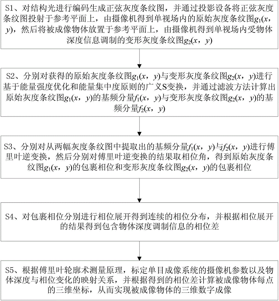
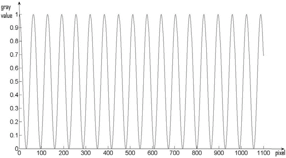
The invention discloses a three-dimensional digital imaging method based on generalized S transformation. The method includes the steps that encoding is carried out on structured light to generate a sine gray scale fringe pattern, an original gray scale fringe pattern in a single field of view and a deformational gray scale fringe pattern modulated by object depth information are obtained by a video camera; generalized S transformation based on energy intensity optimization and an encircled energy principle is carried out, and the fundamental component of the gray scale fringe pattern is calculated based on a filtering method; Fourier inversion is carried out on the fundamental component, and then a wrapping phase of the deformational gray scale fringe pattern is obtained by obtaining phase angles; phase unwrapping is carried out on the wrapping phase and the phase difference between the original gray scale fringe pattern and the deformational gray scale fringe pattern is obtained according to an unwrapping result of the phase; three-dimensional coordinates of each point of an object to be imaged are calculated based on the Fourier transform profilometry measurement principle and the phase difference. The three-dimensional digital imaging method has the advantages of being high in accuracy, wide in adaptability and capable of being widely applied to the fields of three-dimensional digital imaging and optical three-dimensional reconstruction.

Description

technical field [0001] The invention belongs to the fields of three-dimensional digital imaging and optical three-dimensional reconstruction, and in particular relates to a three-dimensional digital imaging method based on generalized S transform. Background technique [0002] The application of optics to three-dimensional digital imaging is an emerging subject area in recent years, and has been further developed into precise three-dimensional measurement technology, which is widely used in industrial measurement, quality inspection, machine vision, intelligent machine control and biomedical diagnosis and many other aspects. At present, the methods for three-dimensional digital imaging by projecting structured light on the object to be imaged and obtaining the phase information from the structured light mainly include Moire profilometry, phase measurement profilometry and Fourier transform profilometry. Moiré profilometry uses Moiré fringe projection, but this method cannot ...

Claims


Application Information

Patent Timeline
IPC IPC(8): G01B11/25G06F19/00G06T7/00
Inventor 李东颜思晨田劲东
Owner SHENZHEN UNIV
Why Eureka
Try Eureka