
Three-dimensional digital imaging method based on space lattice projection

A technology of three-dimensional digital and imaging method, which is applied in the field of three-dimensional digital imaging technology, can solve the problems of difficult phase unwrapping, low sampling efficiency, and inapplicability to real-time measurement, and achieve the effect of alleviating data incompleteness and improving sampling efficiency

Inactive Publication Date: 2005-05-18
SHENZHEN UNIV
View PDF2 Cites 17 Cited by
  • Summary
  • Abstract
  • Description
  • Claims
  • Application Information

AI Technical Summary

Problems solved by technology

[0003] Using the method of single-beam point structure illumination, since only one point is measured at a time, in order to form a complete digital image of a three-dimensional object, two-dimensional scanning must be added. This method has low sampling efficiency and long measurement time, and is not suitable for real-time measurement; Using the line-structured lighting method of sheet-like beams, the structured lighting system projects a sheet-like beam onto the surface of the measured object to form line-structured lighting, which still requires one-dimensional scanning to form a complete three-dimensional object digital image; phase measurement profilometry What is projected is a two-dimensional figure to the measured object to form surface structured illumination, and a complete three-dimensional object digital image can be obtained in one measurement. Phase measurement profilometry has high measurement speed and accuracy, but because the calculated phase distribution is The truncation is within the main value range of the inverse trigonometric function. If the measured object has complex topology or large surface fluctuations, there will be a problem of phase ambiguity when performing phase unwrapping, which is a very difficult problem for phase unwrapping.

Method used


Image

  • Three-dimensional digital imaging method based on space lattice projection
  • Three-dimensional digital imaging method based on space lattice projection
  • Three-dimensional digital imaging method based on space lattice projection

Examples


Embodiment Construction

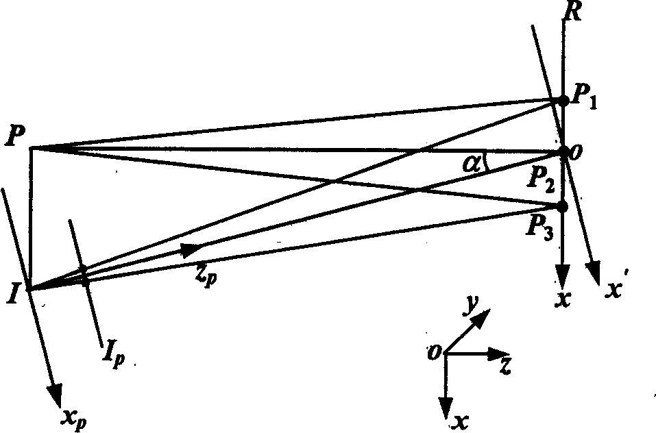
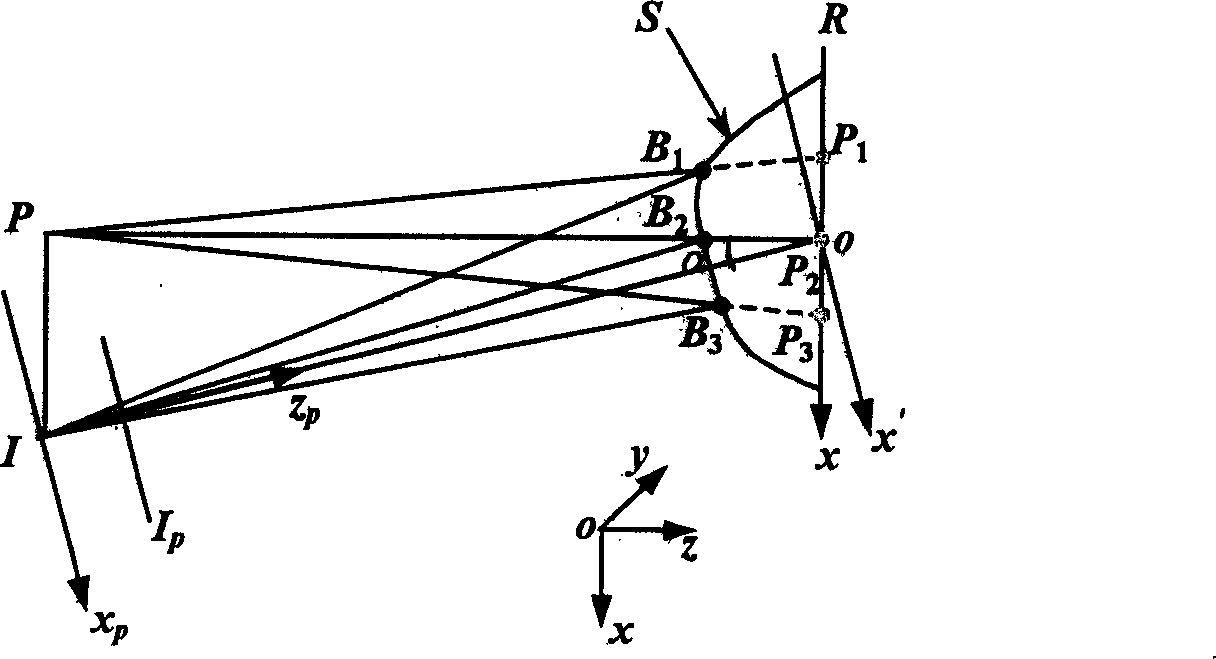
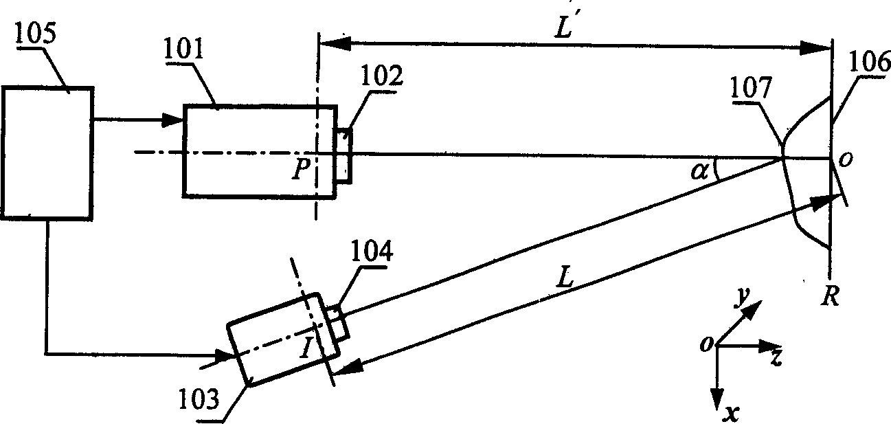
[0043] According to the above method, the device for realizing the three-dimensional digital imaging of spatial lattice projection mainly includes a digital projection illumination transmitter, an image sensor receiver and an image processor. The said digital projection illumination transmitter can be a digital liquid crystal projection device (LCD projector), a digital micro-mirror projection device (DMD projector) or a silicon substrate liquid crystal projection device (LCOS projector), which can be conveniently used by a computer image processing system Generate two-dimensional dot patterns with different densities and write them into the digital projection device; the image sensor receiver includes an optical imaging lens and a photodetector. The optical imaging lens can be a fixed focal length or a variable focal length imaging lens or Lens group, binary optical imaging system, diffraction element imaging system, microscopic imaging system; the photodetector device can be a c...


PUM


Abstract

The present invention discloses one 3D digital imaging method based on space lattice projection, and belongs to the field of 3D digital imaging technology. The method adopts one image device comprising digital projecting and lighting emitter, image sensing receiver and image processor. The emitter projects light in 2D lattice structure to the surface of the object, and constitutes triangular measurement system with the triangles including the base line connecting the exit pupil of the emitter and the entrance pupil of the image sensing receiver and the center of the points of the projected lattice on the object. The lattice image on the reference plane and the lattice image on the measured object surface image sensing receiver obtains are compared in the 'lattice pair' positions to obtain the depth image of the object. The present invention has relatively high sampling efficiency and relatively high practicability on free curved surface with complicated topological structure.

Description

Technical field [0001] The invention relates to a three-dimensional digital imaging method based on spatial lattice projection, which belongs to three-dimensional digital imaging technology. Background technique [0002] In the active three-dimensional sensing technology based on triangulation, based on traditional triangulation, the spatial modulation of the structured illumination beam caused by the surface shape of the three-dimensional object changes the angle of the imaging beam, that is, changes the imaging point in the detection The position on the sensor array is calculated by determining the position of the imaging light spot and the geometric parameters of the optical path of the system. Existing technologies include: a single beam spot structured lighting method and a sheet beam line structured lighting method, as well as phase measurement profilometry, including phase shift profilometry, Fourier transform profilometry, and spatial phase detection profilometry. The pha...

Claims


Application Information

Patent Timeline
Patent Type & Authority Applications(China)
IPC IPC(8): G01B11/24G02B27/22
Inventor 彭翔田颈东牛憨笨
Owner SHENZHEN UNIV
Learn More