Equipment and method for single-cylinder type selective laser melting and milling composite processing

A laser selective melting and compound processing technology, applied in the field of 3D printing of metal parts, can solve the problems that it is difficult to produce high-precision metal parts that meet the requirements, restrict the application and development of SLM technology, and cannot meet the actual requirements, so as to save the follow-up Effects of surface treatment, shortening of powder spreading stroke, and reduction of molding quality

Active Publication Date: 2015-04-08
SOUTH CHINA UNIV OF TECH
View PDF5 Cites 42 Cited by
  • Summary
  • Abstract
  • Description
  • Claims
  • Application Information

AI Technical Summary

Problems solved by technology

Under a certain overlap rate, the final surface of the molded part will have many uneven stripes, resulting in the surface roughness of the metal parts formed by laser selective melting and melting. Generally, the surface roughness is Ra15-50μm. meet actual requirements
Although a small light spot can slightly improve the molding accuracy, the use of a small light spot will seriously reduce the molding efficiency
Existing SLM equipment is difficult to produce high-precision metal parts that meet the requirements, which seriously restricts the application and development of SLM technology

Method used


Image

  • Equipment and method for single-cylinder type selective laser melting and milling composite processing
  • Equipment and method for single-cylinder type selective laser melting and milling composite processing
  • Equipment and method for single-cylinder type selective laser melting and milling composite processing

Examples


Embodiment

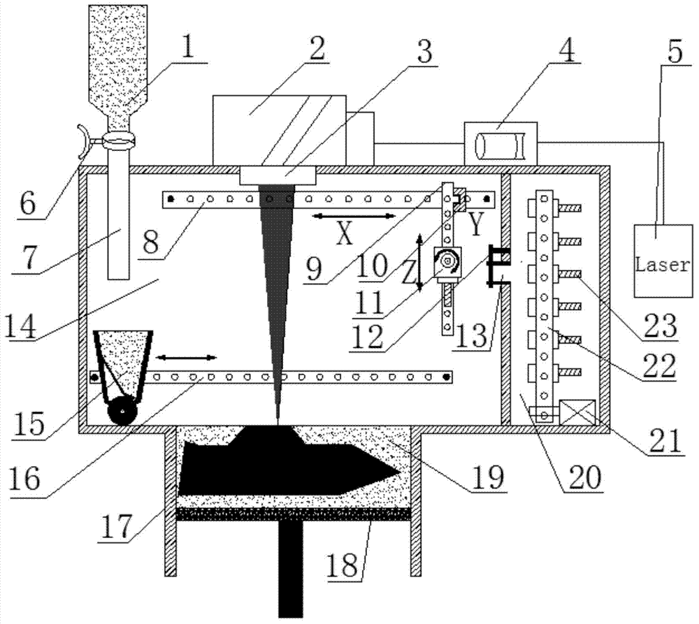
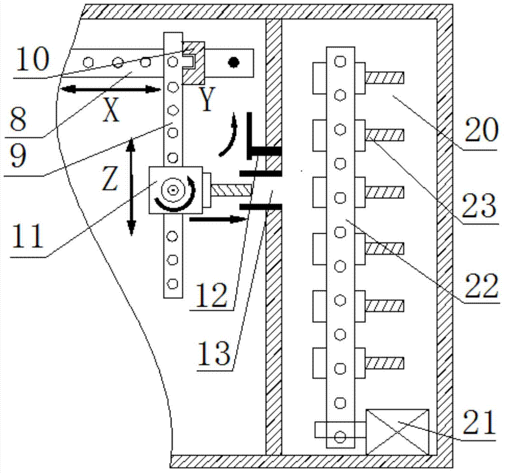
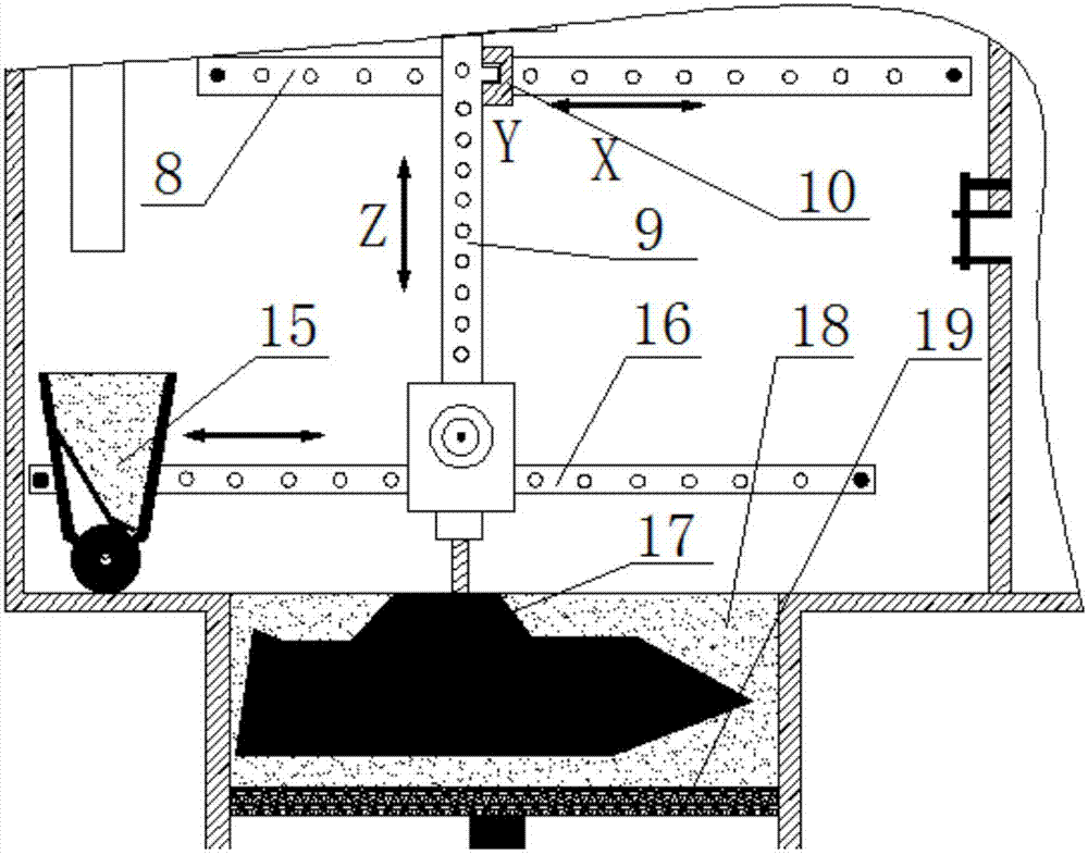
[0039] Such as Figure 1-3 shown. The single-cylinder type laser selective melting and milling compound processing equipment of the present invention includes a laser selective melting forming device and a vertical milling machine device, a central control system, and a laser selective melting forming device includes an optical system, a powder spreading system, a forming chamber 14 and a forming cylinder 18. The laser selective melting forming device and the vertical milling machine share the same central control system.

[0040] The vertical milling machine device is located in the molding chamber 14, and the vertical milling machine device also includes a chain tool magazine 20, and the chain tool magazine 20 is located on the right side outside the molding chamber;

[0041]The optical system includes a laser 5, a collimating beam expander 4, an optical lens 3, and a scanning galvanometer 2 sequentially connected by an optical path;

[0042] The laser 5 is located on the ...


PUM


Abstract

The invention discloses equipment and a method for single-cylinder type selective laser melting and milling composite processing. The equipment comprises a selective laser melting forming device, a vertical milling machine device and a central control system, wherein the vertical milling machine device is positioned in a forming chamber and comprises a chain type tool magazine, the chain type tool magazine is positioned at the right side of the exterior of the forming chamber, a laser device is positioned at the right side of the forming chamber of the selective laser melting forming device, a collimating beam expander, an optical lens and a scanning vibration lens are arranged at the top part of the forming chamber, and the optical lens is positioned at the upper part of the forming chamber, is embedded in the outer wall of the forming chamber, and is in sealed combination with the outer wall of the forming chamber. The equipment has the advantages that the size accuracy and surface quality of a forming part are improved, so the organic combination of additive manufacturing and high-accuracy milling processing is realized; by closing an automatic tool switching valve and a tool switching opening, the influence on a milling tool caused by metal powder and residual heat during laser processing is avoided, the quality of the milling tool is guaranteed, and the service life is prolonged.

Description

technical field [0001] The present invention relates to the 3D printing technology of metal parts, and in particular to a single-cylinder laser selective melting and milling combined processing equipment and method. Background technique [0002] Selective Laser Melting (SLM) technology, also known as "metal 3D printing technology", is the cutting-edge technology of additive manufacturing. It uses a focused laser beam with a diameter of 30-50 microns to melt metal or alloy powder layer by layer and accumulate it into A metallurgically bonded, densely-structured entity, resulting in functional metal parts of almost any shape with complete metallurgical bonding. [0003] SLM equipment is mainly composed of laser, optical path system, sealed forming chamber, mechanical transmission system, control system and other parts. The process flow is as follows: firstly, the 3D CAD model is sliced ​​discretely and the scanning path is planned to obtain the slice profile information that ...

Claims


Application Information

Patent Timeline
Patent Type & Authority Applications(China)
IPC IPC(8): B23P23/04B22F3/105
CPCB22F3/105B23P23/04Y02P10/25
Inventor 杨永强白玉超刘洋王迪
Owner SOUTH CHINA UNIV OF TECH
Why Eureka
Try Eureka