Recycling technology for valuable metals in electrolytic zinc leach residues and electrolytic cell adopted by same
A technology for leaching slag and valuable metals from electrolytic zinc, which is applied in the direction of photographic technology, photographic auxiliary technology, instruments, etc., can solve problems such as difficulty in meeting the requirements of concentrate grade, inability to treat waste slag alone, environmental hazards of drainage and slag discharge, etc. Metal recovery rate and work efficiency, saving the number of components, the effect of reducing the harm to the environment by the amount of the chemical
- Summary
- Abstract
- Description
- Claims
- Application Information
AI Technical Summary
Problems solved by technology
Method used
Image
Examples
Embodiment 1
[0052] A process for extracting valuable metals from electrolytic zinc waste slag in this embodiment comprises the following steps:
[0053] S1 Grinding: First add waste residue and water to the ultrafine grinder at a mass ratio of 2:1, and add sulfuric acid and hydrogen peroxide with a concentration greater than 90%, wherein sulfuric acid and hydrogen peroxide account for 10% and 1% of the total mass of the solution, respectively, At the same time, the ultra-fine grinder is heated to 70°C-90°C, and ground for 30 minutes under normal pressure; since the zinc in the waste residue has been roasted before, it becomes zinc ferrite which is difficult to leach, and cadmium is also difficult to leach, so it is used Mechanical activation can be better leached;
[0054] S2 leaching: put the mixture obtained after grinding into a mixing tank, and add water to the mixing tank until the liquid-solid ratio is 5-8:1, and supplement sulfuric acid and hydrogen peroxide at the same time, so th...
Embodiment 2
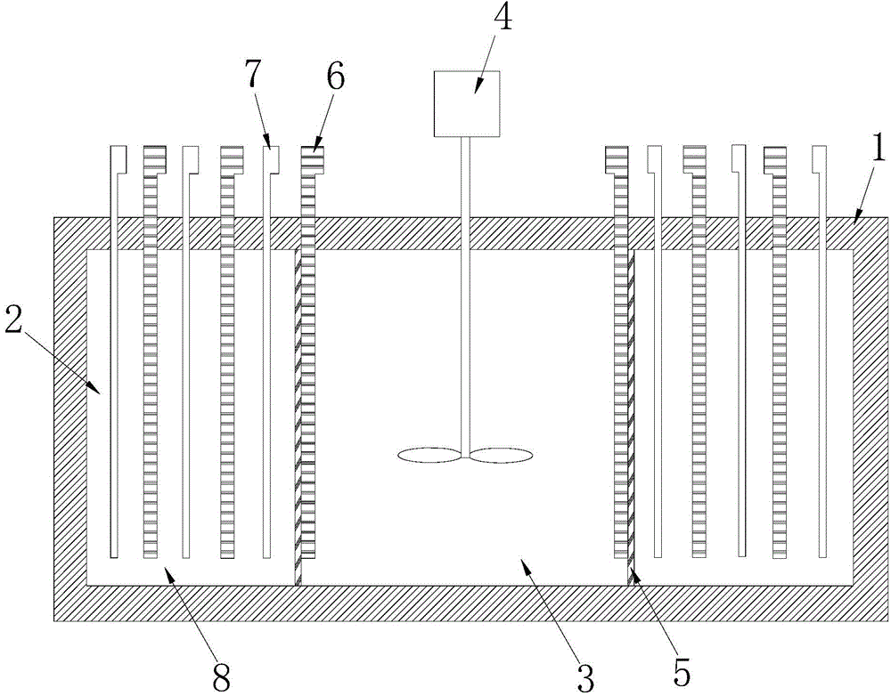
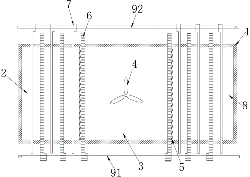
[0078] Such as figure 1 and figure 2 As shown, the electrolytic cell used in the recovery process of valuable metals in a kind of electrolytic zinc leaching slag of this embodiment includes a leaching tank 1, the two ends of the leaching tank 1 are cathode regions 2, and the middle part of the leaching tank 1 is an anode Area 3, the anode area 3 is provided with a stirring mechanism 4, the cathode area 2 at both ends and the anode area 3 in the middle are separated by two diaphragms 5, and an anode plate and a cathode plate are respectively arranged inside and outside the diaphragm 5 to form a diaphragm anode 6 and diaphragm cathode 7; two cathode plates and two anode plates are arranged at intervals in the cathode area 2 to form two groups of electrolysis areas 8 without separation, the cathode plate and the anode plate are respectively connected to a power bus, and the cathode plate is connected to the cathode The bus bar 91 and the anode plate are connected to the anode b...
PUM
 Abstract
Description
Claims
Application Information
 - R&D
- Intellectual Property
- Life Sciences
- Materials
- Tech Scout
- Unparalleled Data Quality
- Higher Quality Content
- 60% Fewer Hallucinations
Browse by: Latest US Patents, China's latest patents, Technical Efficacy Thesaurus, Application Domain, Technology Topic, Popular Technical Reports.
© 2025 PatSnap. All rights reserved.Legal|Privacy policy|Modern Slavery Act Transparency Statement|Sitemap|About US| Contact US: help@patsnap.com


