Application method of cold field plasma discharge assisted high energy ball milled powder and plasma assisted high energy ball milling device

A plasma, high-energy ball milling technology, applied in the field of machinery manufacturing and powder metallurgy, can solve the problems of heavy pollution, high energy consumption of mechanical alloying, low efficiency, etc., to accelerate the refinement and promote the alloying process, efficient ball milling, avoid burn effect

Active Publication Date: 2015-04-29
SOUTH CHINA UNIV OF TECH
View PDF11 Cites 38 Cited by
  • Summary
  • Abstract
  • Description
  • Claims
  • Application Information

AI Technical Summary

Problems solved by technology

[0009] The purpose of the present invention is to overcome the shortcomings of high energy consumption, low efficiency, and heavy pollution of mechanical alloying, and use dielectric barrier discharge (DBD for short) as a unique discharge form that has attracted much attention to generate plasma, and the dielectric barrier discharge The discharge electrode rod is introduced into the high-speed vibrating ball mill jar. On the one hand, it is required that the solid insulating medium on the outer layer of the electrode rod can withstand the high-voltage discharge and the mechanical impact damage of the grinding ball. On the other hand, it is required that the high-speed vibration ball mill device can make the powder treatment effect Uniform, providing a new type of high-energy ball milling device that effectively improves the mechanical alloying efficiency of materials and its application method for preparing cemented carbide, lithium-ion batteries, and hydrogen storage alloy powder materials

Method used


Image

  • Application method of cold field plasma discharge assisted high energy ball milled powder and plasma assisted high energy ball milling device
  • Application method of cold field plasma discharge assisted high energy ball milled powder and plasma assisted high energy ball milling device
  • Application method of cold field plasma discharge assisted high energy ball milled powder and plasma assisted high energy ball milling device

Examples


Embodiment 1

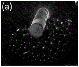
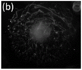
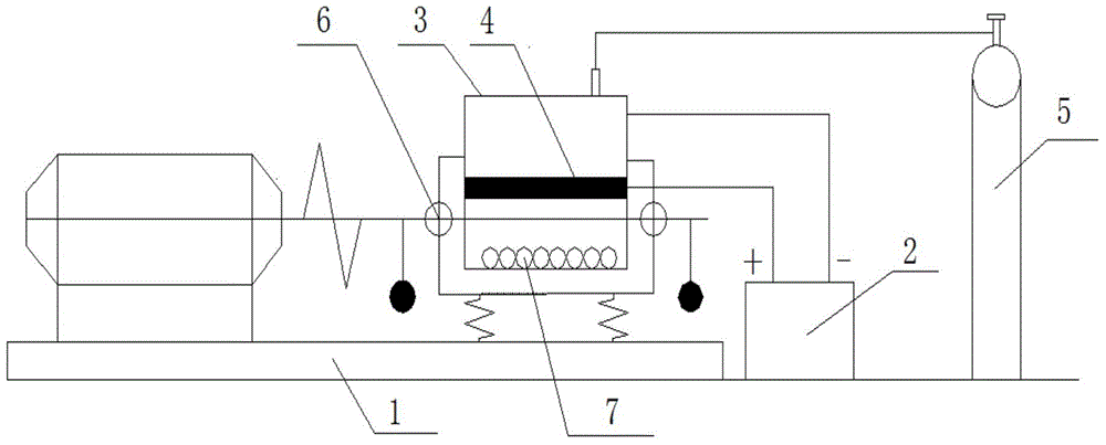
[0087] Step 1. Use the inner copper core and the outer polytetrafluoroethylene to form the electrode rod. The fastening end and the outer layer of polytetrafluoroethylene insulation use threaded cooperation, and the discharge end adopts a polished rod structure (abandon the threaded structure), and in The gap between the electrode layer and PTFE is fully filled with heat-resistant glue to avoid the existence of air, and the top of the electrode adopts a spherical structure to match the outer insulating medium. Install the electrode rod in a 4L ball mill jar, and fill the ball mill jar with grinding balls and powder to be processed, and place the dielectric barrier discharge electrode rod at the center of the ball mill jar, so that the electrode rod is in contact with the ball mill and the powder to be processed , and then use the end cap of the ball mill jar for sealing and fixing. Among them, the diameter of the electrode rod is 25mm, the grinding ball is made of hard alloy m...

Embodiment 2

[0092] Step 1, step 2, same as example 1;

[0093] Step 3, same as example 1, but the rotating speed of ball mill adopts 960rpm.

[0094] The results show that the service life of the electrode rod can reach about 30 hours.

Embodiment 3

[0096] Step 1, the same as Example 1, but the volume of the ball mill is 0.15L, the diameter of the electrode rod is 20mm, and the grinding ball is made of stainless steel;

[0097] Step 2, same as example 1;

[0098] Step 3 is the same as Example 1, but the discharge current is 1.0A, and the speed of the ball mill is 960rpm.

[0099] The results show that the service life of the electrode rod can reach about 35 hours.


PUM

PropertyMeasurementUnit
thicknessaaaaaaaaaa
particle sizeaaaaaaaaaa

Abstract

The invention provides an application method of cold field plasma discharge assisted high energy ball milled powder and a plasma assisted high energy ball milling device using the cold field plasma discharge assisted high energy ball milling method. The method comprises the following steps: utilizing dielectric barrier discharge to generate plasmas, introducing a dielectric barrier discharge electrode bar into a high-speed vibrating ball-milling tank, on one hand, requiring a solid insulating medium on the outer layer of the electrode bar to simultaneously bear high-voltage discharge and mechanical shock failure of the grinding ball, and on the other hand, requiring the high-speed vibrating ball milling device to uniformly process the powder. The method is based on the ordinary ball milling technology; the processing efficiency and the effect of the ball mill can be greatly improved by the following steps: under a non-heat-balance discharge condition of the pressure that the discharge space pressure is set to be about 102-106 Pa, introducing the discharge plasmas to input another effective energy to the processed powder, promoting the powder to be processed to be subjected to combined action of the mechanical stress effect and the heat effect of the external electric field, and further accelerating refining of the powder and promoting the alloying progress.

Description

technical field [0001] The invention belongs to the technical field of mechanical manufacturing and powder metallurgy, and relates to a high-energy ball mill device, in particular to a cold-field plasma-assisted high-energy ball mill device and its application in preparing cemented carbide, lithium-ion batteries, and hydrogen storage alloy powder materials. Background technique [0002] The method of preparing alloy powder by ordinary high-energy ball milling is one of the most commonly used techniques for nano-micron material preparation and mechanical alloying. Generally, the metal or alloy powder is refined to the nano-micron scale by using high-energy ball mill rotation or vibration, that is: two Or two or more powders are put into the ball milling tank of the high-energy ball mill at the same time for ball milling, and the powder particles are rolled, pressed, crushed, and then pressed repeatedly (that is, repeated cold welding-crushing-cold welding), The powder grain a...

Claims


Application Information

Patent Timeline
Patent Type & Authority Applications(China)
IPC IPC(8): B02C17/00B02C17/14B02C17/18B02C17/22B02C23/18
CPCB02C17/14B02C23/06B02C23/24B02C2019/183
Inventor 朱敏曾美琴鲁忠臣欧阳柳章王辉胡仁宗
Owner SOUTH CHINA UNIV OF TECH
Why Eureka
Try Eureka