Direct driven high-speed turbine vacuum pump and operation method thereof

A vacuum pump and high-speed technology, applied in the field of direct-drive high-speed turbo vacuum pump, can solve the problems of many hidden trouble spots, high power consumption or water consumption, and large loss of speed-up transmission, so as to achieve low construction and operation costs, and easy dynamic supply and demand. Balance, the effect of variable frequency and variable speed range

Active Publication Date: 2015-04-29
杭州萧山美特轻工机械有限公司
View PDF8 Cites 7 Cited by
  • Summary
  • Abstract
  • Description
  • Claims
  • Application Information

AI Technical Summary

Problems solved by technology

[0003] Water ring vacuum pump is a relatively common variable capacity low-pressure vacuum pump. The rotor with multi-blade impeller is eccentrically installed in the pump body. When rotating, water is used as the working fluid, and suction, compression and exhaust are realized by the change of the volume of the pump chamber. Gas, so it needs to consume water and the energy consumption acting on water. Its efficiency is currently about 50%, and its speed is generally lower than 3000r / min. The control range is very limited. After a certain point, the water ring will collapse
[0004] In addition, ZL200710071245.3 "cantilever high-speed turbo vacuum pump and its vacuum pumping method", ZL200810219408.2 "a multi-stage turbo vacuum machine and its application Flat vacuum pump and its vacuum pumping method”, the above-mentioned turbo vacuum pumps all drive the speed increase box to achieve high speed through the motor and coupling. , The mechanical transmission efficiency loss of the bearing is about 10% and the energy consumption at the cooling fan, the maintenance is complicated, the floor area is large, and the mechanical failure points at the gearbox and the coupling are increased, and it is difficult to achieve a variable suction process with a fixed speed transmission Necessary and other disadvantages; for multi-stage turbo vacuum pumps, once a failure occurs, the entire production line will be stopped, seriously affecting normal production and causing great economic losses, and the maintenance period is long
[0005] According to the lack of high power consumption or water consumption of positive displacement vacuum pumps, and at the same time aiming at the shortcomings of ordinary fixed-speed high-speed turbo vacuum pumps, such as large speed-up transmission loss and many hidden dangers of failure points, combined with high-efficiency, high-speed, compact, and large pumping capacity of turbo vacuum pumps and other advantages, while meeting the requirements of different pumping volumes and vacuum degrees, it can maximize production efficiency and minimize production losses caused by failures. Further consider a new direct-drive single-stage or double-stage high-speed The flat vacuum pump is very valuable in application and practical significance, in order to adapt to the development needs of modern industry in terms of the maximum efficiency and environmental protection of vacuum pumping and compression equipment; this is the starting point of the present invention

Method used


Image

  • Direct driven high-speed turbine vacuum pump and operation method thereof
  • Direct driven high-speed turbine vacuum pump and operation method thereof

Examples


Embodiment 1

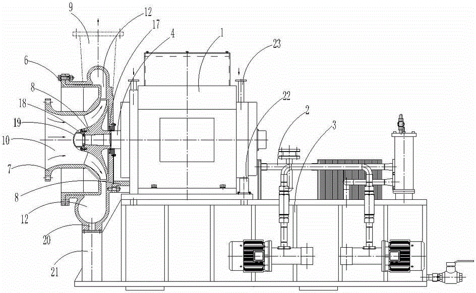
[0043] Embodiment 1: as figure 1 As shown, a direct-drive high-speed turbo vacuum pump includes a direct-connected high-speed motor 1, the direct-connected high-speed motor 1 communicates with a lubricating oil station 2, and the direct-connected high-speed motor 1 is arranged on a platform 3, The direct-coupled high-speed motor 1 is provided with a main shaft 4;

[0044] One end of the direct-coupled high-speed motor 1 is provided with an impeller mechanism, and the impeller mechanism includes a volute 5, a type ring 6 and a turbine impeller 7, and one of the outer ends of the main shaft 4 is provided with a turbine. The impeller 7, the volute 5 is positioned with the direct-connected high-speed motor 1 through the double bracket 8, the turbine impeller 7 is arranged in the volute 5, the main shaft 4 is socketed with the volute 5, The head of the volute 5 is provided with a type ring 6, the outer end of the turbine impeller 7 extends into the type ring 6, the volute 5 commun...

Embodiment 2

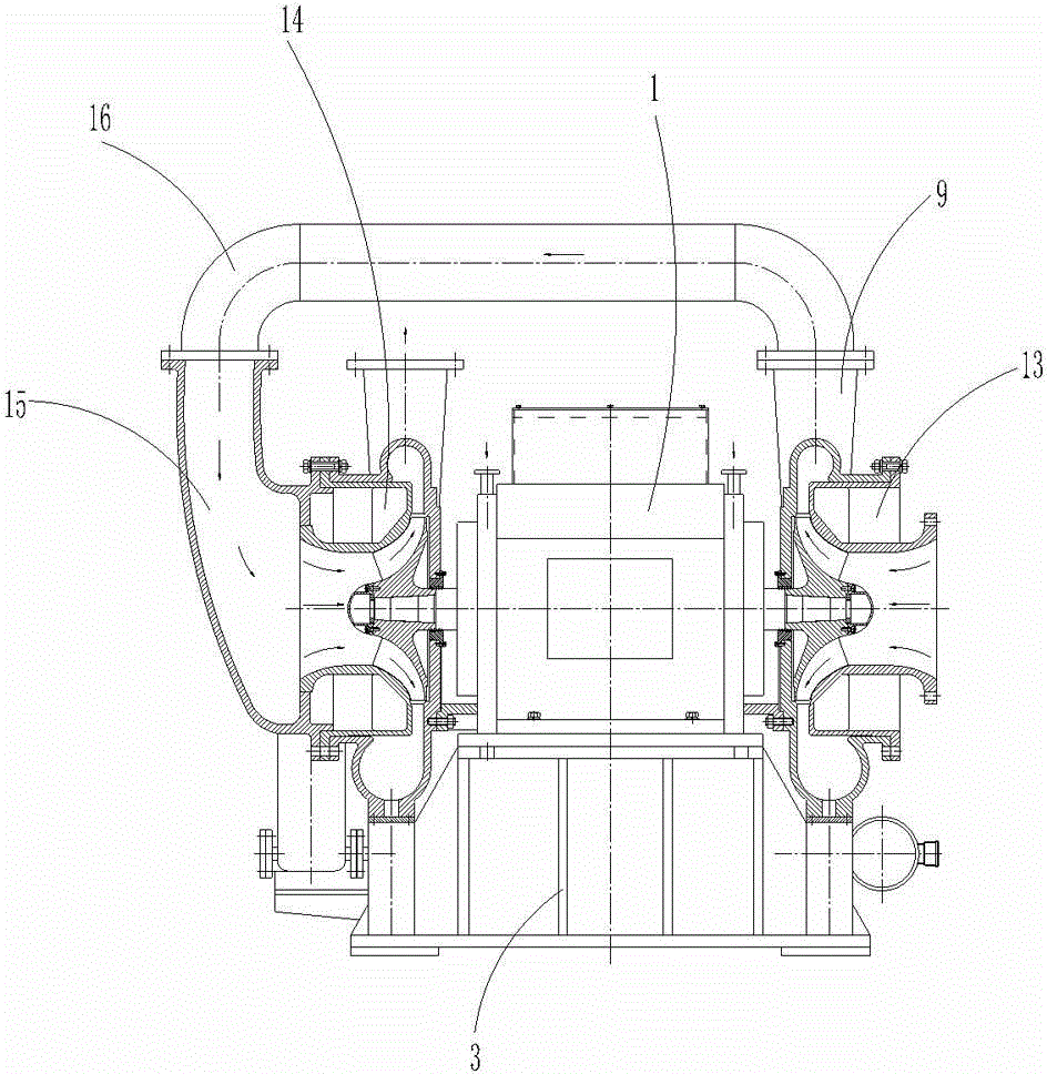
[0059] Embodiment 2: as figure 2 As shown, a direct-drive high-speed turbo vacuum pump includes a direct-connected high-speed motor 1, the direct-connected high-speed motor 1 communicates with a lubricating oil station 2, and the direct-connected high-speed motor 1 is arranged on a platform 3, The direct-coupled high-speed motor 1 is provided with a main shaft 4;

[0060] The left side end of described direct-coupled high-speed motor 1 is provided with left impeller mechanism 13, and the right side end of described direct-coupled high-speed motor 1 is provided with right impeller mechanism 14, and described left impeller mechanism 13 and right impeller mechanism 14 They are respectively arranged at the two ends of the main shaft 4, the structures of the left impeller mechanism 13, the right impeller mechanism 14 and the impeller mechanism are the same, and the outer end of the middle-shaped ring of the left impeller mechanism 13 communicates with the diversion chamber 15, the...


PUM


Abstract

The invention relates to a vacuum pump and especially relates to a direct driven high-speed turbine vacuum pump and an operation method thereof. The direct driven high-speed turbine vacuum pump comprises a direct connected high-speed motor, wherein the direct connected high-speed motor is communicated with a lubricating oil station; the direct connected high-speed motor is arranged on a platform; a spindle is arranged in the direct connected high-speed motor; an impeller mechanism is arranged at one lateral end of the direct connected high-speed motor; or a left impeller mechanism is arranged at the left end of the direct connected high-speed motor, and a right impeller mechanism is arranged at the right end of the direct connected high-speed motor. The method comprises the following steps: assembling and then running at high speed. The direct driven high-speed turbine vacuum pump and the operation method thereof have the advantages that the structure is compact, the use property is promoted, the energy is saved, and the environment is protected.

Description

technical field [0001] The invention relates to a vacuum pump, in particular to a direct-drive high-speed turbo vacuum pump and an operating method thereof. Background technique [0002] As the vacuum application technology has more and more requirements for its pumping capacity and vacuum range in the field of production and scientific research, most of them need to be composed of vacuum pumps and other equipment to form a vacuum pumping system to meet the production and scientific research process. Therefore, there are many situations where a vacuum pumping system composed of different types of vacuum pumps is used for pumping air. Currently, positive displacement vacuum pumps such as rotary vane vacuum pumps, Roots vacuum pumps and water ring vacuum pumps are used, which are mainly used in electric power, Chemical industry, light industry, mining, medicine, electronics, aerospace, scientific research and other departments. [0003] Water ring vacuum pump is a relatively ...

Claims


Application Information

Patent Timeline
Patent Type & Authority Applications(China)
IPC IPC(8): F04D17/10F04D17/12F04D25/06
CPCF04D17/10F04D17/122F04D25/0606
Inventor 戚加友
Owner 杭州萧山美特轻工机械有限公司
Why Eureka
Try Eureka