Manufacturing method of wavelength conversion device

一种波长转换装置、制造方法的技术,应用在照明装置的零部件、放映装置、照明装置等方向,能够解决刮涂工艺要求很高、制作周期长、制造难度大等问题,达到降低制备难度、缩短生产周期、提高热稳定性的效果

Active Publication Date: 2015-04-29
APPOTRONICS CORP LTD
View PDF10 Cites 41 Cited by
  • Summary
  • Abstract
  • Description
  • Claims
  • Application Information

AI Technical Summary

Problems solved by technology

When preparing an integrated multi-color color wheel, due to the large size of the substrate, it is difficult to complete the coating of the powder layer at one time when coating phosphors of different colors, and the requirements for the coating process are very high, and different Due to the different heat resistance properties of phosphors in the color segment, it needs to be scraped and sintered in stages, which is difficult to manufacture and the production cycle is very long

Method used


Image

  • Manufacturing method of wavelength conversion device
  • Manufacturing method of wavelength conversion device
  • Manufacturing method of wavelength conversion device

Examples


Embodiment 1

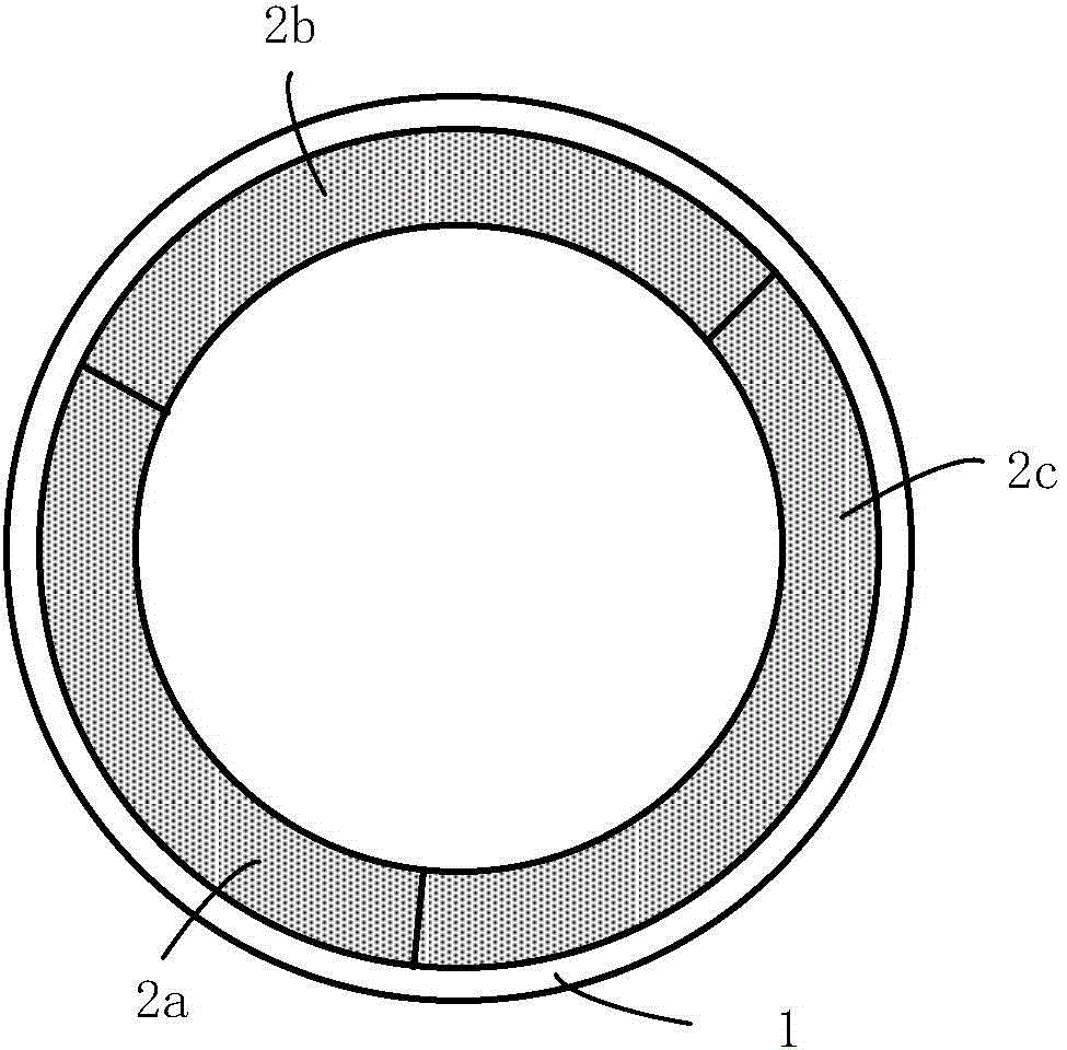
[0042] refer to figure 1 and image 3 , the manufacturing method of the wavelength conversion device is: first prepare three wavelength conversion modules 2a, 2b, 2c respectively, and then install and fix the three wavelength conversion modules on one side surface of a bottom plate 1.

[0043] The manufacturing steps of each wavelength conversion module 2a / 2b / 2c are divided into:

[0044] S1. Prepare diffuse reflection paste and phosphor paste;

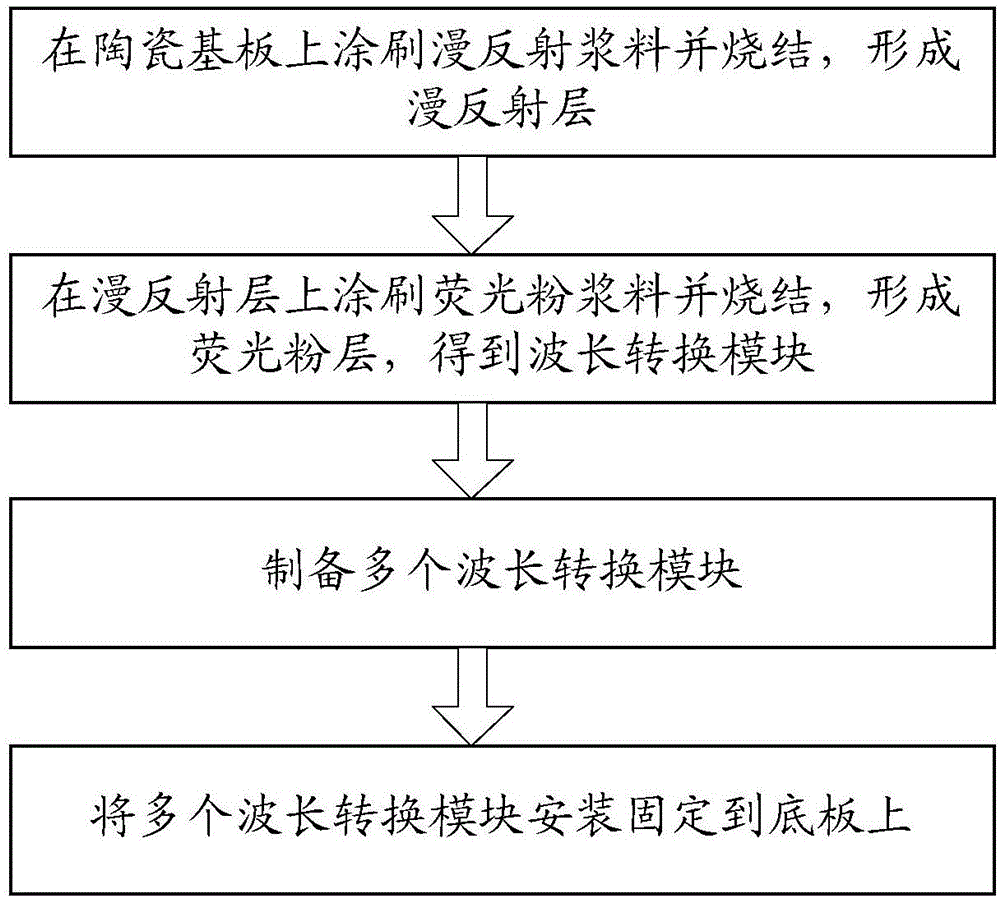
[0045] S2. Brushing the diffuse reflection slurry on the ceramic substrate and sintering to form a diffuse reflection layer;

[0046] S3. Apply phosphor paste on the diffuse reflection layer and sinter to form a phosphor layer to obtain a wavelength conversion module.

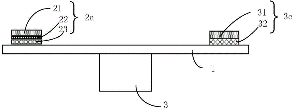
[0047] wavelength conversion module 2a such as figure 2 As shown, it includes a ceramic substrate 23 , a diffuse reflection layer 22 and a phosphor layer 21 , and the three are stacked in sequence and closely attached in pairs.

[0048] In step S1, the diffuse re...

Embodiment 2

[0076] The difference between this embodiment and the first embodiment is that the steps of manufacturing each wavelength conversion module are different, and for other features not described, please refer to the first embodiment.

[0077] like Figure 4 As shown, in this embodiment, the manufacturing steps of the wavelength conversion module are divided into:

[0078] P1. Prepare diffuse reflection paste and phosphor paste;

[0079] P2. Apply phosphor paste on a substrate and sinter to form a phosphor layer;

[0080] P3. Apply diffuse reflection slurry on the phosphor layer and sinter it to form a diffuse reflection layer;

[0081] P4. Demoulding the substrate, taking out a diffuse reflection layer with a phosphor layer attached to one surface, and bonding or sintering the other side of the diffuse reflection layer to the ceramic substrate to obtain a wavelength conversion module.

[0082] Each step is described in detail below.

[0083] For step P1, reference may be made...

Embodiment 3

[0089] The difference between this embodiment and Embodiments 1 and 2 is that some but not all of the wavelength conversion modules are replaced by fluorescent ceramic modules. Therefore, this embodiment is as follows Figure 5 As shown, a part of the wavelength conversion modules are performed according to the steps of the first or second embodiment, as shown in the flow on the left, and the other part is replaced with a fluorescent ceramic module as shown in the flow on the right.

[0090] Correspondingly, the steps for preparing the fluorescent ceramic module are as follows:

[0091] Q1. Obtain fluorescent ceramic blocks;

[0092] Q2. Coating a total reflection dielectric film on the bottom surface of the fluorescent ceramic block.

[0093] Further, step Q3 may also be included:

[0094] Q3: Coating a metal protective film on the outer surface of the total reflection dielectric film.

[0095] like figure 2 As shown, the fluorescent ceramic module 3c thus produced inclu...


PUM

PropertyMeasurementUnit
reflectivityaaaaaaaaaa
melting pointaaaaaaaaaa

Abstract

Disclosed is a manufacturing method for a wavelength conversion device, comprising: preparing a plurality of wavelength conversion modules (2a, 2b, 2c), each wavelength conversion module (2a, 2b, 2c) comprising a ceramic substrate (23), a reflecting layer (22) and a fluorescent powder layer (21), said layers being stacked sequentially and formed into one piece; installing and fixing the plurality of wavelength conversion modules (2a, 2b, 2c) on one surface of a base substrate. By arranging different fluorescent powders respectively on the different wavelength conversion modules (2a, 2b, 2c), a plurality of wavelength conversion modules (2a, 2b, 2c) can be produced separately at the same time, thereby significantly shortening the production cycle. Each such module is produced independently and is thus not subject to the restrictions of the characteristics of other fluorescent powders. This is beneficial for the optimization of the various processes, and a wavelength conversion device having optimal performance is thereby obtained.

Description

technical field [0001] The invention relates to the technical field of illumination and display, in particular to a manufacturing method of a wavelength conversion device. Background technique [0002] Using a solid-state light source such as a laser diode (LD, Laser Diode) or a light-emitting diode (LED, Light Emitting Diode) to emit excitation light to excite phosphors such as phosphors, the wavelength conversion method can produce high-brightness light with a wavelength different from the wavelength of the excitation light. . This solution has the advantages of high efficiency and low cost, and has become the mainstream technology for providing white light or monochromatic light for existing light sources. In this scheme, the light source includes an excitation light source and a color wheel, wherein the color wheel includes a reflective base plate and a phosphor sheet coated on the reflective base plate, and a motor for driving the reflective base plate to rotate, so th...

Claims


Application Information

Patent Timeline
Patent Type & Authority Applications(China)
IPC IPC(8): F21V9/10F21V9/40
CPCF21V9/40G03B21/204G03B33/08H05B33/10G03B21/14C03C17/001G02B5/0242G02B5/0268G02B5/0284G02B26/008
Inventor 李乾许颜正
Owner APPOTRONICS CORP LTD
Why Eureka
Try Eureka