Method for controlling parallel running of micro-grid multi-inverter combination on basis of capacitor voltage differentiation
A multi-inverter, capacitor-voltage technology, applied in the direction of single-network parallel feeding arrangement, etc., can solve the problems of accurate power distribution, increase of current distortion rate, difficulty in realization, etc., and achieve the goal of reducing design workload and reducing circulating current Effect
- Summary
- Abstract
- Description
- Claims
- Application Information
AI Technical Summary
Problems solved by technology
Method used
Image
Examples
Embodiment 1
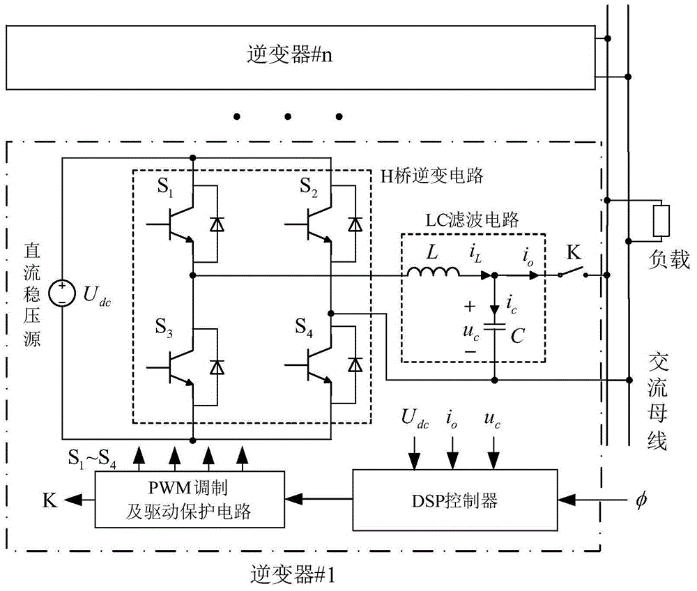
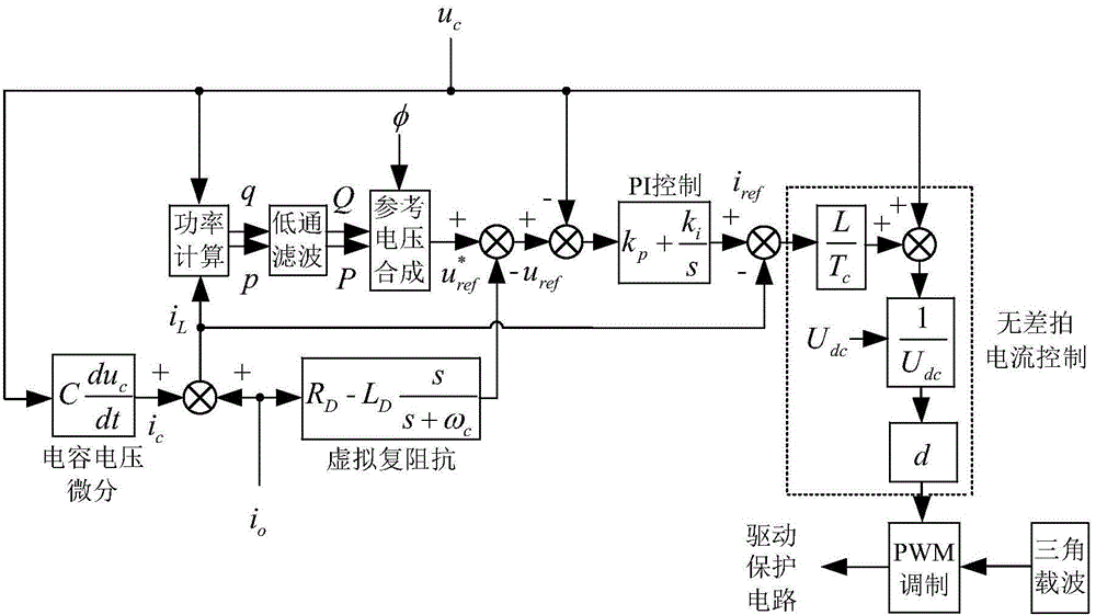
[0069] A micro-grid multi-inverter parallel operation control method based on capacitor voltage differentiation is applicable to a micro-grid multi-inverter parallel control system, and the micro-grid multi-inverter parallel control system includes several parallel inverters, The several parallel inverters are connected to the AC bus through the connecting line through the output relay switch; the inverter includes a sequentially connected DC stabilized voltage source, an H-bridge inverter circuit, and an LC filter circuit; voltage and current transformers The collected electrical quantities are input to the DSP controller for calculation and processing. After the signal output by the DSP controller is modulated by PWM and drives the protection circuit, on the one hand, it drives the switching tube of the H-bridge inverter circuit on and off, and on the other hand, it controls the switching of the output relay switch. Switching, the specific steps include:
[0070] (1) At the ...
Embodiment 2
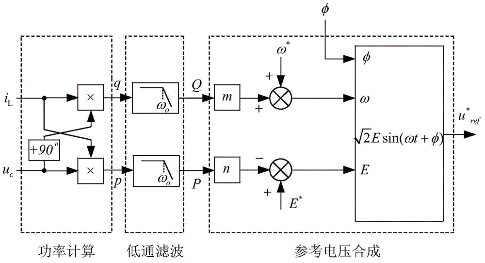
[0091] According to the parallel operation control method described in Embodiment 1, it is further defined as, in step (5), according to the average value of active power P, the average value of reactive power Q, and the initial phase angle φ to synthesize the reference voltage u before introducing the virtual complex impedance * ref , the specific steps are:
[0092] a. Droop control algorithm when the output impedance of the inverter is resistive, u * ref The calculation formula of angular frequency ω and amplitude E of is:
[0093] ω = ω * + mQ E = E * - nP
[0094] In the formula, ω * is the no-load angular frequency reference value, E * is t...
Embodiment 3
[0098] According to the parallel operation control method described in Embodiment 1 or 2, it is further defined that in step (8), the value of the modulation coefficient d is 0.97.
PUM
 Abstract
Description
Claims
Application Information
 - R&D
- Intellectual Property
- Life Sciences
- Materials
- Tech Scout
- Unparalleled Data Quality
- Higher Quality Content
- 60% Fewer Hallucinations
Browse by: Latest US Patents, China's latest patents, Technical Efficacy Thesaurus, Application Domain, Technology Topic, Popular Technical Reports.
© 2025 PatSnap. All rights reserved.Legal|Privacy policy|Modern Slavery Act Transparency Statement|Sitemap|About US| Contact US: help@patsnap.com


