
Lubricating oil base oil production method

A technology for lubricating base oils and production methods, applied in lubricating compositions, the petroleum industry, and treating hydrocarbon oils, etc., can solve problems such as high reaction temperature at the outlet of the bed, limited operating cycle, etc., achieve optimization effects, reduce severity, The effect of saving operating costs

Active Publication Date: 2015-05-13
CHINA PETROLEUM & CHEM CORP +1
View PDF12 Cites 4 Cited by
  • Summary
  • Abstract
  • Description
  • Claims
  • Application Information

AI Technical Summary

Problems solved by technology

Although this method improves the average reaction temperature of the hydrodepressant catalyst and utilizes the temperature rise of the refined preparation to increase the utilization rate of the depreciation catalyst, the reaction temperature at the outlet of each bed is still relatively high, and the operation period is limited by a certain degree. limits

Method used


Image

  • Lubricating oil base oil production method

Examples


Embodiment 1

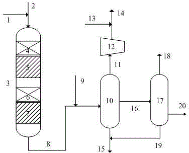
[0043] use figure 1 The process flow shown is to produce lubricating oil base oil by mixing and grading in series. In Example 1, two hydrogenation reaction zones connected in series are included. In the composite bed of the decondensation cracking catalyst in each reaction zone, the mixing volume ratio of the hydrocracking catalyst to the hydrocracking catalyst is 1:2, and the total amount of catalyst used is Both of Comparative Example 1 and Comparative Example 2 are the same. The hydrocracking catalyst used in Example 1 is FC-50 catalyst, and the hydrodecondensation catalyst is FDW-3 catalyst, both of which are commercial catalysts developed and produced by Fushun Petrochemical Research Institute.

[0044] The operating conditions and test results are listed in Table 3.

Embodiment 2

[0046] use figure 1 The process flow shown is to produce lubricating oil base oil by mixing and grading in series. In Example 1, two hydrogenation reaction zones connected in series are included. In the composite bed of the decondensation cracking catalyst in each reaction zone, the mixing volume ratio of the hydrocracking catalyst to the hydrocracking catalyst is 1:2, and the total amount of catalyst used is Both of Comparative Example 1 and Comparative Example 2 are the same. The hydrocracking catalyst used in Example 2 is FC-50G catalyst, and the hydrodecondensation catalyst is FDW-3 catalyst, both of which are commercial catalysts developed and produced by Fushun Petrochemical Research Institute.

[0047] The operating conditions and test results are listed in Table 3.

[0048] Table 2 Raw oil properties table.

[0049] project Raw oil source Decompression wax oil Density(20℃) / g·cm -3 0.8760 Distillation range / ℃ 339~541 Nitrogen / μg·g ...


PUM

PropertyMeasurementUnit
dew pointaaaaaaaaaa
dry pointaaaaaaaaaa
specific surface areaaaaaaaaaaa

Abstract

The present invention discloses a lubricating oil base oil production method. According to the lubricating oil base oil production method of the present invention, a wax oil raw material and hydrogen gas are mixed and then sequentially pass through at least two hydrogenation reaction zones connected in series, wherein each hydrogenation reaction zone sequentially comprises a composite catalyst bed layer filled with a hydrodewaxing catalyst and a hydrocracking catalyst in a mixed manner and a hydrodewaxing catalyst bed layer according to the material flowing direction, and the reaction effluent obtained from the last hydrogenation reaction zone is subjected to separation and fractionation to obtain the lubricating oil base oil, the white oil and other products. With the method of the present invention, the temperature decrease during the hydrodewaxing process and the temperature increase during the hydrogenation process are subjected to reasonable combination utilization, such that the low freezing point lubricating oil base oil is produced while the viscosity index is increased, the hot spot temperature of the device is reduced, and the operation period is prolonged; and the cold hydrogen consumption or the heating furnace fuel gas loss is reduced, and the operating cost is saved.

Description

technical field [0001] The invention relates to a production method of lubricating oil base oil, in particular to a hydrogenation method for producing lubricating oil base oil through catalyst composite loading and gradation technology. Background technique [0002] Lubricant is a very important petroleum product, and it is the key factor to drive moving parts. Although its products only account for about 2% of the crude oil processing volume, there are hundreds of varieties due to the wide variety of use conditions, and the quality The requirements are strict, and lubricating oil is a kind of lubricant. For a wide variety of lubricating oils, it is impossible to produce each of them individually. Therefore, in order to simplify its production, all countries adopt the method of first making lubricating oil base oils that meet certain standards, and then blending and adding additives according to market needs. to produce various products. [0003] It can be seen that althou...

Claims


Application Information

Patent Timeline
Patent Type & Authority Applications(China)
IPC IPC(8): C10G67/02C10M177/00
Inventor 王仲义崔哲彭冲石友良孙士可黄新露吴子明
Owner CHINA PETROLEUM & CHEM CORP
Learn More