Ceramic metal halide lamp electrode and ceramic metal halide lamp
A ceramic metal halide lamp and electrode technology, which is applied in the fields of ceramic metal halide lamp electrodes and ceramic metal halide lamps, can solve problems such as radioactive pollution, production and use, and achieve long service life, extended service life, and electronic work function. low effect
- Summary
- Abstract
- Description
- Claims
- Application Information
AI Technical Summary
Problems solved by technology
Method used
Image
Examples
Embodiment 1
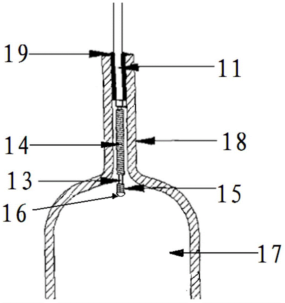
[0041] A ceramic metal halide lamp electrode and a ceramic metal halide lamp. The structure of the electrodes of the ceramic metal halide lamp is as described above and attached figure 2 As shown, wherein, the size of the relevant parts in the ceramic metal halide lamp electrode is as described in Example 1 in Table 1 below; the percentage by weight of dysprosium in the electrode rod 13 is 0.2%; the electrode tip 16 is a hemisphere, and its dysprosium-tungsten alloy The weight percentage of dysprosium is 0.2%, and the radius of the hemisphere is 0.5mm; one end of the tungsten helix 15 is fixedly connected with the electrode head 16, and the length of the tungsten helix 15 is 0.7mm, and the length of the electrode rod 13 is 3mm.
[0042] The ceramic metal halide lamp is arranged in the discharge cavity 17. The luminescent pill is composed of sodium iodide, thallium iodide and indium iodide according to the molar ratio of 0.01:6.6×10 -4 :4.4×10 -5 Prepared, its preparation me...
Embodiment 2
[0046] A ceramic metal halide lamp electrode and a ceramic metal halide lamp. The structure of the electrodes of the ceramic metal halide lamp is as described above and attached figure 2 As shown, wherein, the size of the relevant parts in the ceramic metal halide lamp electrode is as described in Example 2 in Table 1 below; the percentage by weight of dysprosium in the electrode rod 13 is 2.0%; the electrode head 16 is a hemisphere, and its dysprosium-tungsten alloy The weight percentage of dysprosium is 2.0%, and the length of the tungsten spiral 15 is 0.7 mm, and the length of the electrode rod 13 is 3 mm.
[0047] The ceramic metal halide lamp is arranged in the discharge chamber 17 and the luminescent pill is as the luminescent pill in Embodiment 1.
[0048] The structure of the ceramic metal halide lamp is as described above and attached image 3 shown. The power of the ceramic metal halide lamp is as described in Example 2 in Table 1 below.
Embodiment 3
[0050] A ceramic metal halide lamp electrode and a ceramic metal halide lamp. The structure of the electrodes of the ceramic metal halide lamp is as described above and attached figure 2 As shown, wherein, the size of the relevant parts in the ceramic metal halide lamp electrode is as described in Example 3 in Table 1 below; the percentage by weight of dysprosium in the electrode rod 13 is 3.0%; the hemispherical electrode tip 16 is a hemisphere, and its dysprosium The weight percentage of dysprosium in the tungsten alloy is 3.0%, and the radius of the hemisphere is 0.5mm; one end of the tungsten spiral 15 is fixedly connected with the electrode head 16, and the length of the tungsten spiral 15 is 0.7mm, and the length of the electrode rod 13 is 3mm.
[0051] The ceramic metal halide lamp is arranged in the discharge chamber 17 and the luminescent pill is as the luminescent pill in Embodiment 1.
PUM
| Property | Measurement | Unit |
|---|---|---|
| diameter | aaaaa | aaaaa |
| diameter | aaaaa | aaaaa |
| power | aaaaa | aaaaa |
Abstract
Description
Claims
Application Information
 - R&D
- Intellectual Property
- Life Sciences
- Materials
- Tech Scout
- Unparalleled Data Quality
- Higher Quality Content
- 60% Fewer Hallucinations
Browse by: Latest US Patents, China's latest patents, Technical Efficacy Thesaurus, Application Domain, Technology Topic, Popular Technical Reports.
© 2025 PatSnap. All rights reserved.Legal|Privacy policy|Modern Slavery Act Transparency Statement|Sitemap|About US| Contact US: help@patsnap.com


