Ceramic metal halide lamp electrode and ceramic metal halide lamp

A ceramic metal halide lamp and electrode technology, applied in the field of ceramic metal halide lamp electrodes and ceramic metal halide lamps, can solve the problems of radioactive pollution, production and use, etc., and achieve the effects of no radioactive pollution, long service life, and impact avoidance

Inactive Publication Date: 2015-05-27
OCEANS KING LIGHTING SCI&TECH CO LTD +2
View PDF0 Cites 0 Cited by
  • Summary
  • Abstract
  • Description
  • Claims
  • Application Information

AI Technical Summary

Problems solved by technology

[0007] The purpose of the present invention is to overcome the above-mentioned deficiencies in the prior art, and provide a thorium-free ceramic metal halide lamp electrode and a ceramic metal halide lamp with zirconium yttrium-tungsten alloy as the electrode rod, aiming at solving the problems of the existing ceramic metal halide lamps and electrodes. Technical problems of radioactive pollution in the production and use of thorium dioxide as a radioactive material

Method used


Image

  • Ceramic metal halide lamp electrode and ceramic metal halide lamp
  • Ceramic metal halide lamp electrode and ceramic metal halide lamp
  • Ceramic metal halide lamp electrode and ceramic metal halide lamp

Examples


Embodiment 1

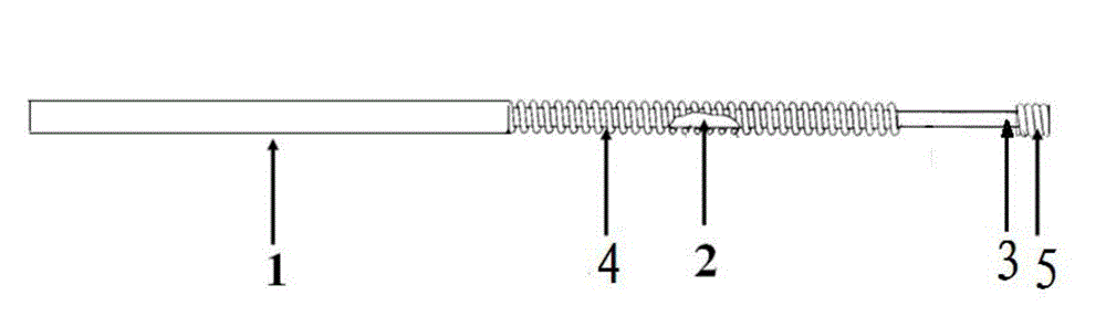
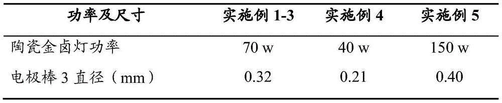
[0039] A ceramic metal halide lamp electrode and a ceramic metal halide lamp. The structure of the electrodes of the ceramic metal halide lamp is as described above and attached figure 1 As shown, wherein, the size of each component in the electrode of the ceramic metal halide lamp is as described in Example 1 in Table 1 below; The molar ratio of the two is 1.5:1; the length of the tungsten helix 5 is 1.7 mm, and the length of the electrode rod 3 is 5 mm.

[0040] The molar ratio of sodium iodide, thallium iodide and indium iodide in the luminescent pill 6 in the ceramic metal halide lamp arranged in the discharge chamber 7 is 0.01:6.6×10 -4 :4.4×10 -5 . Its preparation method is as follows:

[0041] Set the molar ratio to 0.01:6.6×10 -4 :4.4×10 -5 After the sodium iodide, thallium iodide and indium iodide were mixed uniformly to form a mixture, it was placed in a quartz container with a nozzle, pre-vacuumized at 130 ° C for 50 minutes, then slowly heated until the mixtu...

Embodiment 2

[0044] A ceramic metal halide lamp electrode and a ceramic metal halide lamp. The structure of the electrodes of the ceramic metal halide lamp is as described above and attached figure 1 As shown, wherein, the size of each component in the electrode of the ceramic metal halide lamp is as described in Example 2 in Table 1 below; The molar ratio of the two is 1.5:1; the length of the tungsten helix 5 is 1.7 mm, and the length of the electrode rod 3 is 5 mm.

[0045] The ceramic metal halide lamp is arranged on the luminescent pill 6 in the discharge chamber 7 as the luminescent pill in the first embodiment. The preparation method of luminescent pill 6 refers to Example 1.

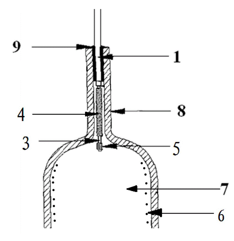
[0046] The structure of the ceramic metal halide lamp is as described above and attached figure 2 shown. The power of the ceramic metal halide lamp is as described in Example 2 in Table 1 below.

Embodiment 3

[0048] A ceramic metal halide lamp electrode and a ceramic metal halide lamp. The structure of the electrodes of the ceramic metal halide lamp is as described above and attached figure 1 As shown, wherein, the size of each component in the electrode of the ceramic metal halide lamp is as described in Example 3 in Table 1 below; The molar ratio of the two is 1.5:1; the length of the tungsten helix 5 is 1.7 mm, and the length of the electrode rod 3 is 5 mm.

[0049] The ceramic metal halide lamp is arranged on the luminescent pill 6 in the discharge chamber 7 as the luminescent pill in the first embodiment. The preparation method of luminescent pill 6 refers to Example 1.

[0050] The structure of the ceramic metal halide lamp is as described above and attached figure 2 shown. The power of the ceramic metal halide lamp is as described in Example 3 in Table 1 below.


PUM

PropertyMeasurementUnit
diameteraaaaaaaaaa
diameteraaaaaaaaaa
diameteraaaaaaaaaa

Abstract

The invention discloses a ceramic metal halide lamp electrode and a ceramic metal halide lamp. The ceramic metal halide lamp electrode comprises an outgoing line, a connecting rod and an electrode bar, which are sequentially and coaxially connected, wherein molybdenum spirals are wound on the outer surface of the connecting rod; tungsten spirals are wound on the outer surface of the other end part, opposite to the connecting end of the connecting rod, of the electrode bar; the electrode bar is made of zirconium yttrium tungsten alloy formed by zirconium oxide, yttrium oxide and tungsten metal; the total weight percent of zirconium oxide and yttrium oxide is 0.2-3%; the molar ratio of zirconium oxide to yttrium oxide is (1-2.5):1. According to the ceramic metal halide lamp electrode disclosed by the invention, the low current requirement during fast triggering of gas is effectively ensured, so that impact of the high current to a lamp tube is avoided, the service life of the lamp is prolonged, no radioactive contamination is achieved, and high safety and environment protection during production and use are achieved. The ceramic metal halide lamp adopts the ceramic metal halide lamp electrodes as positive and negative electrodes, and is environment-friendly, safe, high in luminous efficiency, good in color rendering index and color temperature, and long in service life.

Description

technical field [0001] The invention belongs to the technical field of lighting and optoelectronics, and in particular relates to a ceramic metal halide lamp electrode and a ceramic metal halide lamp. Background technique [0002] In recent years, the development of ceramic metal halide lamp technology has become more and more mature, the performance parameters have been greatly improved and far surpassed the traditional quartz metal halide lamp in all aspects, and its use has begun to spread rapidly. Even so, the performance of ceramic metal halide lamps has yet to be perfected. [0003] As an important part of the ceramic metal halide lamp, the electrode structure directly affects the performance of the metal halide lamp. At present, the commonly used electrodes for low-power ceramic metal halide lamps in the world can be divided into lead wires (mainly composed of niobium), connecting rods (mainly composed of molybdenum) and electrode rods (mainly composed of thoriated t...

Claims


Application Information

Patent Timeline
Patent Type & Authority Applications(China)
IPC IPC(8): H01J61/073H01J61/82C22C27/04
CPCH01J61/073C22C27/04H01J61/0735
Inventor 周明杰段永正
Owner OCEANS KING LIGHTING SCI&TECH CO LTD
Why Eureka
Try Eureka