Method and device for strengthening oil-water separation and coupled desalting functions in cold low pressure separator

A cold and low-pressure separator, oil-water separation technology, applied in separation methods, chemical instruments and methods, liquid separation, etc., can solve the problems of increasing downstream load, ineffective removal, poor liquid-gas separation effect, etc., to improve coalescence. Performance, not easy to break and emulsification, to achieve the effect of deep desalination

Active Publication Date: 2015-06-03
EAST CHINA UNIV OF SCI & TECH
View PDF8 Cites 15 Cited by
  • Summary
  • Abstract
  • Description
  • Claims
  • Application Information

AI Technical Summary

Problems solved by technology

[0003] At present, the low-pressure separator adopts the conventional gravity settling tank for separation, and there are three problems in the operation process: (1) The liquid-gas separation effect is poor, because the dispersed micro-bubbles separated by the depressurization flash cannot be effectively settled by gravity Removed, entrained into acidic water or distillate oil, resulting in loss of gas resources (mainly hydrogen), and will also increase the downstream load; (2) Oil and water are separated by gravity sedimentation, and the design residence time is 10 minutes or longer. The effect is poor and the floor area is large; (3) After the oil quality deteriorates, the amount of salt and hydrogen sulfide in the distillate increases, the dehydration effect of the distillate is poor, and the hydrogen sulfide and salt in the water cause corrosion in the downstream steaming and fractionation process Seriously, the current design does not take into account the desalination function of the low pressure separator

Method used


Image

  • Method and device for strengthening oil-water separation and coupled desalting functions in cold low pressure separator

Examples


Embodiment 1

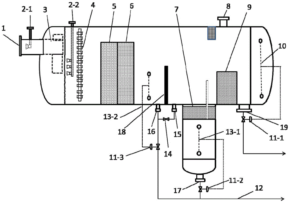
[0036] Such as figure 1 As shown, the oil-water separation and coupling desalination functional device in the enhanced cold and low-pressure separator includes a shell, an oil-water-gas inlet 1 arranged on the shell, a water injection port 2-1 connected to the oil-water-gas inlet 1 and a T-shaped liquid Gas separator 3 (or cyclone degasser), secondary water injector (including water injection port 2-2), rectifier distributor 4, oil-water coarse-graining module 5, CPI quick separation module 6 arranged in sequence inside the shell , (oil-water) interface controller 13-1, 13-2, partition 18, liquid level controller 10 and oil phase outlet 19 at the tail of the housing; the depth degreasing module 7 placed at the bottom of the housing, the The top has a gas phase outlet 8; the bottom of the shell is also provided with a water phase outlet 17. The oil phase outlet 10, the water phase outlet 17, and the water phase outlet 16 are respectively provided with regulating valves 11-1, 1...


PUM

PropertyMeasurementUnit
particle diameteraaaaaaaaaa

Abstract

The invention relates to a method and a device for strengthening oil-water separation and coupled desalting functions in a cold low pressure separator. The method comprises the following steps: performing countercurrent mixing on water-containing low-content oil and desalted water with the volume ratio of 0-1 percent at the inlet section, allowing the mixture to enter a T-shaped liquid-gas separator for being subjected to degassing treatment, rapidly separating the gas phase subjected to step-down flash in the low-content oil, and allowing the oil-water mixture to flow to a rectification distributor on the lower part of the low-pressure separator from a left seal head to a right seal head so as to realize uniform distribution on the radial section; rapidly separating the oil water by virtue of a coarse graining module and a CPI module sequentially, discharging one part of water, allowing oil and trace water (0-0.01 percent) to enter a deep separation section by virtue of a separator, performing deep dehydration on the oil by virtue of a fiber combined module, discharging the oil, performing further deep deoiling on the intercepted water by virtue of the combined fiber module, and discharging the water. According to the method and the device disclosed by the invention, the oil-water separation performance of the cold low pressure separator can be strengthened, the desalting function in the oil can be realized, the occupied area of the low pressure separator is reduced, and the defects of the conventional low pressure separator are overcome.

Description

technical field [0001] The invention relates to the field of petroleum refining or coal chemical industry, and relates to a method and a device for strengthening oil-water separation and coupling desalination functions in a cold low-pressure separator. Background technique [0002] In the hydrogenation unit, the working principle of the low-pressure separator belongs to the equilibrium vaporization in the distillation operation, that is, after the feed is decompressed in a certain way, in a container space, at a certain temperature and pressure, steam, The liquid and liquid phases are separated immediately to obtain the corresponding gas and liquid phase products. The function of the low-pressure separator is to separate the gas-liquid phase components in the incoming material of the cold high-pressure separator, flash off some gas-phase components, and reduce the gas-phase load of the fractionation system; secondly, because the gas-phase components contain more sulfide Hyd...

Claims


Application Information

Patent Timeline
Patent Type & Authority Applications(China)
IPC IPC(8): B01D17/022B01D17/032B01D17/02B01D17/038B01D17/05B01D19/00
CPCB01D17/02B01D17/0214B01D17/0217B01D17/047B01D19/0052B01D17/12B01D19/00C10G53/02C10G2300/205C10G2300/805B01D17/045B01D19/0036
Inventor 杨强卢浩刘森许萧王朝阳
Owner EAST CHINA UNIV OF SCI & TECH
Why Eureka
Try Eureka