Direct-reduction ironmaking method and system for iron-containing mineral powder

A technology for iron ore powder and reduced iron, which is applied in the field of direct reduction iron-making methods and systems containing iron ore powder, can solve the problems of complex process equipment and low reduction efficiency, and achieves simple reduction process, high reduction efficiency, and shortened reaction time. effect of time

Active Publication Date: 2015-06-03
湖南长拓高科冶金有限公司
5 Cites 16 Cited by

AI-Extracted Technical Summary

Problems solved by technology

[0008] The present invention aims to provide a direct reduction ironmaking method and system for iron-containing ore powder to solve the commo...

Method used

By comparison of comparative example 3 and each embodiment, it can be seen that the Midrex method of comparative example 3 has a higher metallization rate, but the reaction time is several hours, strict requirements on ore granularity, and complex process equipment; and this The various examples of the application not only shorten the reaction time greatly, but also have a higher metallization rate; in addition, through the comparison of the examples and comparative examples 1 to 2, it can be found that the application controls the volume of hydrogen and carbon monoxide in the reducing gas and reduces The control of temperature can guarantee a higher metallization rate; further, through the comparison of embodiment 2 and embodiments 6 to 9, it is found that within a certain reaction time, whether preheating, preheating temperature, hydrogen in reducing gas and The volume ratio of carbon monoxide and the particle size of iron-containing ore powder will have a certain impact on the metallization rate.
Carbon monoxide content is higher in the oxygen-enriched coal gas, for better meeting the needs of the application's flash reduction, utilize gas adjustment unit 11 to increase the content of hydrogen, make hydrogen and carbon monoxide volume ratio be (0.8~1.5) in reducing gas : 1, the adjustment process can use the conversion furnace to convert part of the carbon monoxide into hydrogen and carbon dioxide through the reaction of carbon monoxide and water; the carbon dioxide content in the oxygen-enriched gas after conversion is too large, and the required reducing gas content rises when the reduction reaction is fully carried out However, the complete progress of the reaction is affected, and the above-mentioned carbon dioxide removal unit 12 is used to remove or reduce the content of carbon dioxide, satisfying that the sum of the volumes of hydrogen and carbon monoxide in the reducing gas is greater than 70% of the total volume of the reducing gas, and then ensuring that the reduction reaction is carried out completely. It is beneficial to improve the metallization rate of the product; the above-mentioned gas heating unit 13 is set to heat the reducing gas, so that the reducing gas entering the flash reduction device 200 is a high-temperature gas, which meets the requirements of 800-1000°C, 20-120S Internal flash reduction of iron-containing ore powder. The above-mentioned gas heating unit 13 is preferably an indirect heat exchange furnace, which can avoid pollution to the formed reducing gas during the heat exchange process.
In order to further accelerate the speed of the reduction reaction, preferably before step S1, the direct reduction ironmaking method of the above-mentioned iron-containing ore powder also includes an adjustment step, so that the hydrogen and carbon monoxide volume ratio (0.8~1.5) in the reducing gas: 1. It is found through experiments that the addition of hydrogen at 800-1000 °C can accelerate the reduction re...

Abstract

The invention provides a direct-reduction ironmaking method and system for iron-containing mineral powder. The direct-reduction ironmaking method for the iron-containing mineral powder comprises the following steps: S1, carrying out flash reduction on the iron-containing mineral powder with a reducing gas at 800-1,000 DEG C, and finishing reducing reaction within 20-120 seconds to obtain a mixture containing direct-reduced iron and a tail gas; S2 carrying out gas-solid separation on the mixture, and respectively obtaining the direct-reduced iron and the tail gas, wherein the volume sum of hydrogen and carbon monoxide in the reducing gas is greater than 70% of the total volume of the reducing gas. In the implementation process of the method, iron-containing mineral powder is in a suspended flow state, and has great heat and mass transfer ability between a gas and solid; and the heat and mass transfer ability is over 50 times of accumulation state reaction, therefore, the direct-reduction ironmaking system has an extremely high reaction speed; the reaction time can be greatly shortened; the reaction speed can be accelerated by the reducing gas; complete reduction reaction is promoted; an intermediate reduction product is avoided; and improvement of the metal conversion rate is facilitated.

Application Domain

Fluidised-bed furnaces

Technology Topic

Image

  • Direct-reduction ironmaking method and system for iron-containing mineral powder
  • Direct-reduction ironmaking method and system for iron-containing mineral powder
  • Direct-reduction ironmaking method and system for iron-containing mineral powder

Examples

  • Experimental program(9)
  • Comparison scheme(3)

Example Embodiment

[0053] Example 1
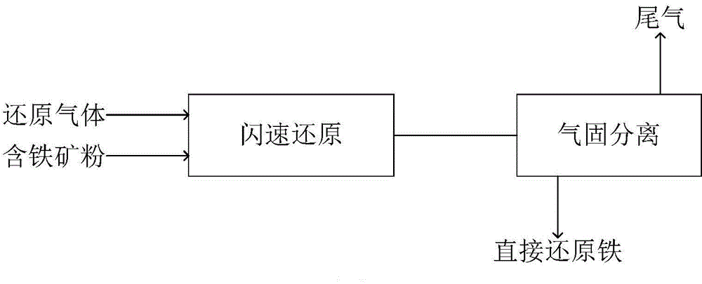
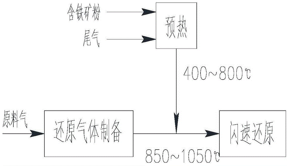
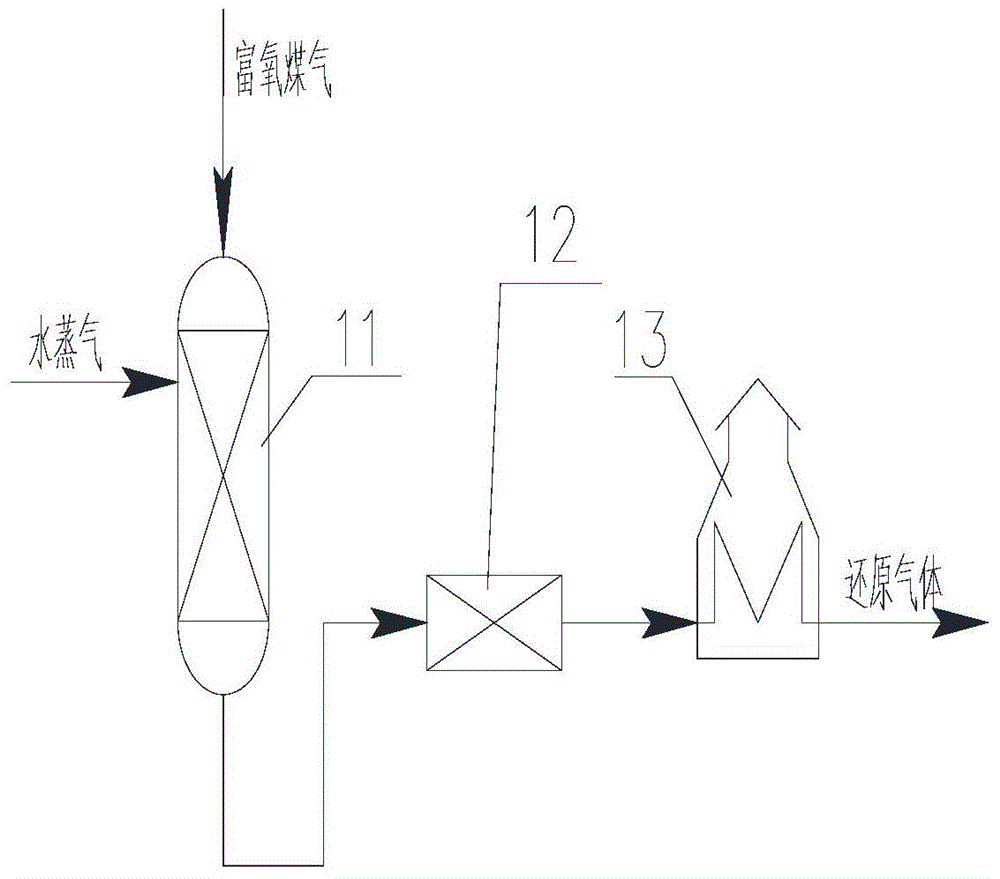
[0054] The oxygen-enriched gas from the gas furnace is passed into the shift furnace, and in the shift furnace (as a gas conditioning unit), part of the CO is consumed by the reaction of CO and steam and hydrogen is generated, and H is adjusted. 2 The volume ratio to CO is 0.8:1, and the shift gas enters CO 2 Removal device, remove or reduce most of the CO 2 , Make CO and H 2 The total concentration is about 80%, and then it is heated to about 950℃ in the heating furnace to complete the preparation of reducing gas; limonite powder with an iron grade of about 50% and a particle size of less than 0.05mm enters the cyclone preheater from the metering device to be preheated to At about 700℃, it enters the flash reduction furnace after preheating. In the flash reduction furnace, the reducing gas contacts the preheated iron-bearing ore powder and the reduction reaction occurs at 800℃. After 30-40S, it enters the cyclone separator together and directly The reduced iron is discharged from the lower part of the cyclone separator, and after cooling, direct reduced iron is obtained. After testing, the metallization rate of the product is 95%; the tail gas enters the cyclone preheater from the upper part of the cyclone separator to preheat the cold ore powder; The exhaust gas is discharged from the upper part of the cyclone preheater and enters the gas heat exchanger to heat the oxygen-enriched air for gas production or the air required for combustion in the hot blast stove. The temperature of the exhaust gas is further reduced; it enters the bag filter to remove the dust in the exhaust gas; after dust removal The exhaust gas from the exhaust gas enters the scrubbing tower to further remove the dust in the exhaust gas. Part of the scrubbed exhaust gas is used as fuel gas for heating; the other part can be used as a blending gas and oxygen-enriched gas to prepare reducing gas for recycling.

Example Embodiment

[0055] Example 2
[0056] Pipeline natural gas is passed into the reformer to be catalytically reformed into CO and H 2 Mixture, control H 2 The volume ratio to CO is 1.2:1, CO+H 2 The concentration is about 90%, and the gas temperature of the reforming furnace is controlled to 900℃ to complete the preparation of the reducing gas; enter the flash reduction furnace; iron fine powder with an iron grade of about 63% and a particle size of less than 0.074mm enters the cyclone preheating from the metering device The device is preheated to 750℃ and enters the flash reduction furnace after preheating. In the flash reduction furnace, the reducing gas contacts the preheated iron-bearing ore powder and the reduction reaction occurs at 800℃. After 20-30S, it enters the cyclone separation together. The reduced iron is discharged from the lower part of the cyclone separator. After cooling, direct reduced iron is obtained. After testing, the metallization rate of the product is 97%; the tail gas enters the cyclone preheater from the upper part of the cyclone separator to preheat the cold ore powder; The exchanged tail gas is discharged from the upper part of the cyclone preheater and enters the gas heat exchanger to heat the oxygen-enriched air for gas production or the air required for combustion in the hot blast stove. The temperature of the tail gas is further reduced; it enters the bag filter to remove the dust in the tail gas; The dust-removed tail gas enters the scrubber to further remove the dust in the tail gas. Part of the scrubbed tail gas is used as fuel gas for heating; the other part can be used as a blended gas and natural gas to prepare reducing gas for recycling.

Example Embodiment

[0057] Example 3
[0058] Pipeline natural gas is passed into the reformer to be catalytically reformed into CO and H 2 Mixture, control H 2 The volume ratio to CO is 1:1, CO and H 2 The total volume reaches about 75%, and the output temperature of the reformer is controlled to 1050℃ to complete the preparation of reducing gas; enters the flash reduction furnace; hematite powder with an iron grade of 45% and a particle size of less than 0.1mm enters the cyclone from the metering device The preheater is preheated to 500℃, and then enters the flash reduction furnace after preheating. In the flash reduction furnace, the reducing gas contacts the preheated iron-containing ore powder and the reduction reaction occurs at 850℃, and then enters together after 100~120S In the cyclone separator, the reduced iron is discharged from the lower part of the cyclone separator. After cooling, direct reduced iron is obtained. The metallization rate of the product is 95%. The tail gas enters the cyclone preheater from the upper part of the cyclone to preheat the cold ore powder; the tail gas after heat exchange is discharged from the upper part of the cyclone preheater and enters the gas heat exchanger to heat the air required for combustion in the drying hot blast stove. The exhaust gas temperature is further reduced; the exhaust gas enters the bag filter to remove the dust in the exhaust gas; the exhaust gas after dust removal enters the scrubber to further remove the dust in the exhaust gas, and part of the exhaust gas after washing is used as fuel gas for heating; the other part can be used as mixed gas and natural gas for heating Prepare reducing gas and recycle it.

PUM

PropertyMeasurementUnit
Granularity<= 0.1mm
Granularity<= 0.038mm
Granularity<= 0.074mm
tensileMPa
Particle sizePa
strength10

Description & Claims & Application Information

We can also present the details of the Description, Claims and Application information to help users get a comprehensive understanding of the technical details of the patent, such as background art, summary of invention, brief description of drawings, description of embodiments, and other original content. On the other hand, users can also determine the specific scope of protection of the technology through the list of claims; as well as understand the changes in the life cycle of the technology with the presentation of the patent timeline. Login to view more.

Similar technology patents

Method and device for catalytic hydrolysis of urea

ActiveCN103395801AFast responseImprove securityAmmonia preparation/separationAutomatic controlDiammonium phosphate
Owner:DATANG ENVIRONMENT IND GRP +1

Ultrasonic-assisted microwave controllable preparation method of Cu2ZnSnS4 nano-particles

InactiveCN103420411AFast responseAvoid expensive vacuum equipmentMaterial nanotechnologyTin compoundsQuantum dotLithium electrode
Owner:NANJING UNIV OF AERONAUTICS & ASTRONAUTICS

Coal gas production method

Owner:KEDA INDUSTRIAL GROUP CO LTD +1

Classification and recommendation of technical efficacy words

  • Fast response
  • Short reaction time

Systems and methods for integrating focal plane arrays

ActiveUS20070170359A1Reduce thermal response timeFast responseTelevision system detailsSpectrum investigationReadout integrated circuitMulti spectral
Owner:L 3 COMM CORP

High speed and wide viewing angle liquid crystal displays

InactiveUS20050024548A1Fast responseInput data rate be relatively highNon-linear opticsThin-film-transistor liquid-crystal displayLiquid-crystal display
Owner:UNIV OF CENT FLORIDA RES FOUND INC +1

High-concentration fast preparation method for silver nanowires

InactiveCN101934378AShort reaction timeImprove reaction efficiency and equipment utilizationCopper chlorideMother liquor
Owner:ZHEJIANG UNIV

Foliar compound fertilizer and preparation method thereof

Owner:万物生(深圳)生物科技控股有限公司
Why Eureka
Try Eureka