Flexible pyroelectric thin film device

A thermoelectric thin film and device technology, which is applied in the directions of thermoelectric device components, thermoelectric device manufacturing/processing, thermoelectric device junction lead wire materials, etc. practical problems, to achieve the effect of enhanced bonding force, reliable deposition, and high reliability

Inactive Publication Date: 2015-06-10
STATE GRID CORP OF CHINA +2
View PDF6 Cites 29 Cited by
  • Summary
  • Abstract
  • Description
  • Claims
  • Application Information

AI Technical Summary

Problems solved by technology

At present, the thermoelectric materials used in flexible thermoelectric devices that have come out are generally organic thermoelectric materials, but the Seebeck coefficient α and electrical conductivity σ of organic thermoelectric materials are quite low, and the thermoelectric performance is far lower than that of inorganic thermoelectric materials such as bismuth telluride. used in practice; and inorganic thermoelectric materials are difficult to be used in flexible thermoelectric devices due to their own brittleness
On the other hand, the preparation methods of organic thermoelectric materials are mainly printing methods or chemical methods, etc., and the binding force between the prepared thermoelectric materials and the substrate is very weak.
[0004] In fact, inorganic thermoelectric materials can be flexible and efficient through thin film, but the difficulty lies in how to achieve high bonding force between inorganic thermoelectric thin films and flexible substrates to ensure high reliability of flexible thermoelectric thin film devices

Method used


Image

  • Flexible pyroelectric thin film device
  • Flexible pyroelectric thin film device
  • Flexible pyroelectric thin film device

Examples


Embodiment 1

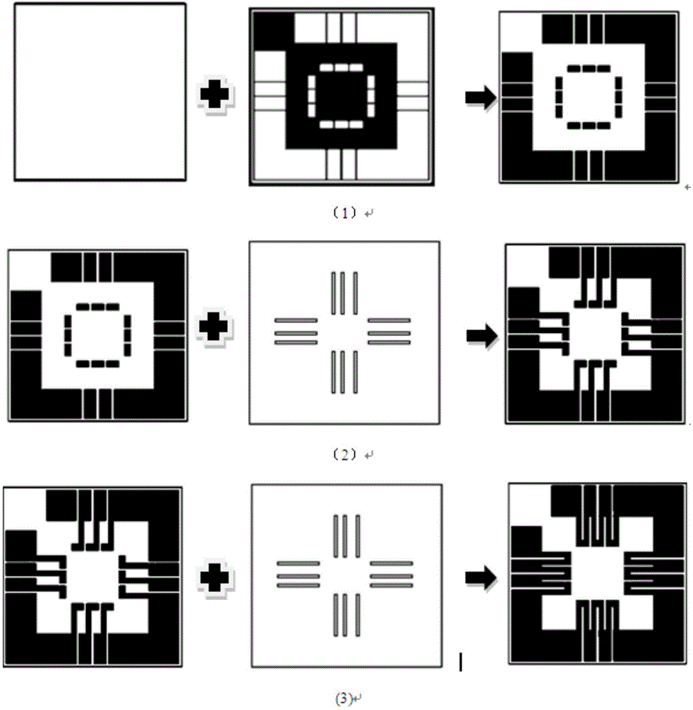
[0045] According to the preparation method in the present invention, it is sputtered at normal temperature, and the thermoelectric arm is 6mm long such as figure 1 The flexible thermoelectric thin film device shown. Its preparation process is as follows: ① use a magnetron sputtering apparatus and an electrode mask to press figure 1 Step (1) in the preparation of Cu electrode film and Ni transition layer. The parts that do not need to be sputtered are covered with an electrode mask. Under the pressure of 1.5Pa, the sputtering power of 30W, and the substrate temperature of 100°C, the copper electrode film is sputtered on the polyimide flexible substrate with a magnetron sputtering device for 2 hours. , and then sputter nickel transition layer 0.25h. ②Use a magnetron sputtering apparatus and a BST thermoelectric material mask to press figure 1 Step (2) in prepares BST (Bi 2-x Sb x Te 3 , x=1.2~2.0) thermoelectric thin film. The parts that do not need to be sputtered are co...

Embodiment 2

[0048] According to the preparation method in the present invention, a flexible thermoelectric thin film device with a sputtering temperature of 350° C. and a thermoelectric arm of 6 mm in length is prepared. The preparation process is as follows: ①Use a magnetron sputtering apparatus and an electrode mask figure 1 Step (1) in the preparation of Cu electrode film and Ni transition layer. Use an electrode mask to cover the part that does not need to be sputtered, and adjust the magnetron sputtering instrument to sputter copper on the polyimide flexible substrate under the conditions of air pressure 1.5Pa, sputtering power 30W, and substrate temperature 100°C Electrode thin film 2h, then sputter nickel transition layer 0.25h. ② Using magnetron sputtering and BST (Bi 2-x Sb x Te 3 , x=1.2~2.0) The thermoelectric material mask is pressed figure 1 Step (2) in the preparation of BST thermoelectric thin film. Use an electrode mask to cover the part that does not need to be sputt...

Embodiment 3

[0051]According to the preparation method in the present invention, a flexible thermoelectric thin-film device with a thermoelectric arm length of 8 mm, a sputtering temperature of 350° C., and annealing at 350° C. for 1 h is prepared. The preparation process is as follows: ①Use a magnetron sputtering apparatus and an electrode mask according to figure 1 Step (1) in the preparation of Cu electrode film and Ni transition layer. Use an electrode mask to cover the part that does not need to be sputtered, and adjust the magnetron sputtering instrument to sputter the copper electrode film for 2 hours under the conditions of air pressure 1.5Pa, sputtering power 30W, and substrate temperature 100°C, and then sputter Ni transition layer 0.25h. ② Using magnetron sputtering and BST (Bi 2-x Sb x Te 3 , x=1.2~2.0) The mask plate of thermoelectric material is pressed figure 1 In step (2) to prepare BST thermoelectric thin film, cover the parts that do not need to be sputtered with an ...


PUM

PropertyMeasurementUnit
particle sizeaaaaaaaaaa

Abstract

The invention discloses a flexible pyroelectric thin film device. The device comprises a polyimide flexible substrate, a copper electrode thin film, a nickel transition layer and pyroelectric thin films, the particles of the pyroelectric thin film are arranged in a gradient mode on particle diameter, the pyroelectric thin films comprise a P type pyroelectric thin film and an N type pyroelectric thin film, the P type pyroelectric thin film and the N type pyroelectric thin film are connected through the copper electrode thin film, the p-n thermoelectric couple pairs arranged in an array mode and serially connected are formed on the flexible substrate for forming the flexible pyroelectric thin film device having in-plane structure. The sputtering parameter and the heat treatment process are adjusted and controlled for optimizing microcosmic interfacial structure of the thin film material, the inorganic thin film can be reliably deposited on the flexible substrate and the reliable flexible pyroelectric thin film device with high performance is prepared.

Description

technical field [0001] The invention relates to a thermoelectric device, in particular to a flexible thermoelectric thin film device prepared by magnetron sputtering technology. Background technique [0002] Thermoelectric materials are functional materials that can convert heat and electricity into each other, and can be used in the manufacture of thermoelectric generators, refrigerators and sensors. Commonly used thermoelectric materials include inorganic thermoelectric materials and organic thermoelectric materials. The performance of thermoelectric materials is related to three parameters: Seebeck coefficient α, electrical conductivity σ and thermal conductivity κ. The thermoelectric figure of merit ZT (ZT=α 2 σT / κ) is a dimensionless description, in which the electrical part PF(α 2 σ) is called the "power factor"; the higher the power factor of a thermoelectric material, the better its thermoelectric performance. In practical applications, thermoelectric materials are...

Claims


Application Information

Patent Timeline
Patent Type & Authority Applications(China)
IPC IPC(8): H01L35/02H01L35/14H01L35/34
Inventor 邓元祝志祥陈新马光张义政韩钰陈保安
Owner STATE GRID CORP OF CHINA
Why Eureka
Try Eureka