Gas-solid separation and re-coupling type biomass clean combustion device and combustion method

A combustion device and solid-phase combustion technology, applied in the direction of combustion methods, solid fuel combustion, combustion equipment, etc., can solve the problems of not clean combustion, unfavorable miniaturization promotion, scattered overall layout, etc., to achieve easy clean combustion, high air supply volume Reasonable arrangement of combustion field and improvement of combustion efficiency

Active Publication Date: 2015-06-17
ENERGY RES INST OF SHANDONG ACAD OF SCI +1
View PDF9 Cites 6 Cited by
  • Summary
  • Abstract
  • Description
  • Claims
  • Application Information

AI Technical Summary

Problems solved by technology

However, this design also has the following deficiencies: (1) The traditional technical scheme of burning a part of the material to heat another part of the material and pyrolyzing the gas does not make good use of the volatile matter to directly produce synthesis gas, while the solid phase Compared with synthetic gas produced after complex reactions, it is more conducive to the characteristics of stable combustion and heat supply; (2) There is no discussion on the treatment method of solid residues after gasification of materials in the gas phase furnace. If continuous production is carried out, it needs Further design; (3) The overall layout is scattered, which will inevitably cause a large amount of heat loss, which is not conducive to energy saving; (4) There are many components in the device and the cost is high, which is not conducive to miniaturization and popularization among ordinary users
Due to the large relative area of ​​the main grate at the rear end, although local hypoxia is used to control NOx, it is difficult to ensure that the beneficial effects in the early stage will not be offset by the combustion on the main grate, and there is no impact on the resulting NOx. Particulate matter suppression measures are not clean combustion in the full sense

Method used


Image

  • Gas-solid separation and re-coupling type biomass clean combustion device and combustion method
  • Gas-solid separation and re-coupling type biomass clean combustion device and combustion method
  • Gas-solid separation and re-coupling type biomass clean combustion device and combustion method

Examples


Embodiment 1

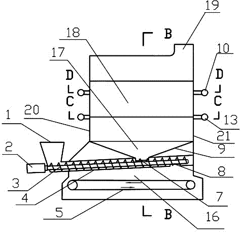
[0025] Embodiment 1: A gas-solid two-phase separation re-coupled biomass clean combustion device, which includes a cuboid furnace and is sequentially arranged in the furnace from bottom to top: a chain grate 5, a solid phase above the chain grate 5 Combustion chamber 16, is positioned at the reduction reaction chamber 17 above solid phase combustion chamber 16, is positioned at the gas phase combustion chamber 18 above reduction reaction chamber 17; Also has the solid phase combustion air supply system that communicates with solid phase combustion chamber 16, and gas phase combustion chamber 18 connected gas-phase combustion primary and secondary air supply systems; a screw conveyor is also provided, and the screw conveyor includes a cylindrical spiral tube 4 and a screw shaft 3 arranged in the spiral tube 4, and a driving motor 2 for driving the screw shaft 3, An open hopper 1 connected to the feed end of the spiral tube 4; the front part of the spiral tube 4 extends into the ...

Embodiment 2

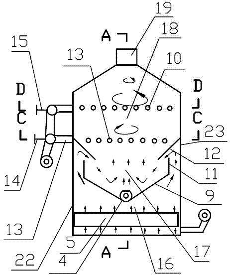
[0033] Example 2: A gas-solid two-phase separation and coupling biomass clean combustion method based on the gas-solid two-phase separation and coupling biomass clean combustion device in Example 1. When the biomass passes through the screw feeder, it is fed by the spiral tube 4 The temperature of the solid-phase combustion below is heated and decomposed into gas-solid two-phase; the gas phase flows along the upward spiral tube to the gas-phase outlet 7, enters the reduction reaction chamber 17, and flows out from the solid-phase combustion chamber 16 through the baffle ribs 6 and After returning to the smoke picking plate 12, most of the particulate matter containing NO x The flue gas is mixed, and the reducing components and NO flowing out of the gas phase outlet 7 x N 2 , to reduce NO in flue gas x The mixed gas after the reduction reaction flows upwards and enters the gas phase combustion chamber 18, and mixes again with the swirl air coming in from the primary swirl air...


PUM


Abstract

A gas-solid separation and re-coupling type biomass clean combustion device comprises a spiral feeding system, a chain furnace grate, a solid combustion chamber, a reduction reaction chamber, a gas combustion chamber, a solid combustion air supply system, a primary gas combustion air supply system, a secondary gas combustion air supply system and a cuboid hearth. The spiral feeding system comprises an open hopper, a drive motor, a feeding shaft with a spiral fin and a spiral pipe. The device is provided with the independent reduction reaction chamber, the independent solid combustion chamber and the independent gas combustion chamber. A combustion method of the gas-solid separation and re-coupling type biomass clean combustion device includes the steps that biomass is firstly dissolved into gas and solid through self heat supply, dust of smoke generated after solid combustion is removed, a reduction reaction is conducted on the smoke and gas generated after thermolysis, and NOx is reduced; primary combustion and secondary combustion are conducted, generation of NOx is controlled, and combustion is thorough.

Description

technical field [0001] The invention relates to a gas-solid two-phase separation re-coupling type biomass clean combustion device and a combustion method thereof in the technical field of new energy clean combustion. Background technique [0002] The 2007 "China Energy Development Report" pointed out that the development and utilization of biomass energy in China is only 1%, and most of them are directly burned and utilized. At the same time, large-scale open burning of straw often leads to smog, causing serious air pollution and climate change. At present, biomass liquefaction and gasification technology cannot realize complete market-oriented operation, and is limited to complex technical conditions. It is only suitable for large-scale transformation and utilization in factories, and cannot adapt to the current situation of China's wide dispersion of biomass energy and high collection costs. . The development of small devices with simple structure, easy operation, and cl...

Claims


Application Information

Patent Timeline
Patent Type & Authority Applications(China)
IPC IPC(8): F23B90/06F23B10/02F23K3/00
Inventor 张晓东司洪宇李勇刚陈雷伊晓路孙来芝孟光范赵保峰
Owner ENERGY RES INST OF SHANDONG ACAD OF SCI
Why Eureka
Try Eureka