Reflective array radiating element and planar reflective array antenna

A technology of radiation unit and reflection array, which is applied in the field of reflection array radiation unit, flat panel reflection array antenna, and radiation unit for microstrip reflection antenna, can solve the problem of increasing the structural complexity and manufacturing cost, increasing the gain of antenna space occupation, and affecting the communication effect. and other problems to achieve the effect of shortening the design cycle, reducing coupling, and avoiding gain loss

Active Publication Date: 2015-06-24
NANJING CLEANWAVE COMM TECH
View PDF10 Cites 7 Cited by
  • Summary
  • Abstract
  • Description
  • Claims
  • Application Information

AI Technical Summary

Problems solved by technology

The former increases the focal-diameter ratio of the antenna, that is, increases the focal length of the feed or reduces the aperture of the front, but this method may increase the space occupied by the antenna due to the use of telephoto or limit the gain due to the small aperture, which affects the communication effect; The latter usually adopts a delay line or a multi-layer structure. The delay line is not only limited by the unit size but also increases the loss as the length of the delay line increases. The multi-layer structure not only increases the loss, but also increases the complexity of the structure. degree and manufacturing cost

Method used


Image

  • Reflective array radiating element and planar reflective array antenna
  • Reflective array radiating element and planar reflective array antenna
  • Reflective array radiating element and planar reflective array antenna

Examples


Embodiment Construction

[0023] The present invention will be described in further detail below in conjunction with the accompanying drawings.

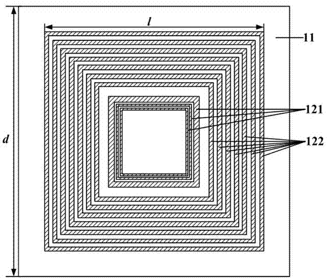
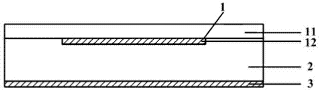
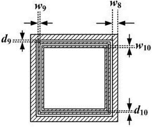
[0024] Such as figure 1 , 2 As shown in and 3 , the reflectarray radiation unit 1 of the present invention is composed of a dielectric substrate 11 and a metal pattern layer 12 printed on the lower side of the dielectric substrate 11 . The metal pattern layer 12 includes a phase factor adjustment ring 121 and a phase compensation ring 122. The above phase factor refers to the slope of the phase frequency response curve, which depends on the relative positions of the reflectarray unit and the feed source. The phase compensation ring 122 is printed on the periphery of the phase factor adjustment ring 121, and the two form a multi-ring nested structure. In this embodiment, both the phase factor adjustment loop 121 and the phase compensation loop 122 adopt a square loop structure, the number of the phase factor adjustment loop 121 is 3, and the number of the ph...


PUM


Abstract

The invention discloses a reflective array radiating element and belongs to the technical field of antennas. The reflective array radiating element comprises a dielectric substrate and a metal pattern layer printed on one side of the dielectric substrate. The metal pattern layer is in a multi-ring nested structure, comprising a plurality of phase factor adjusting rings and a plurality of phase compensation rings located outside the phase factor adjusting rings. The use of the single-layer printed structure allows easier process of the multi-layer printing technique, lower dielectric loss and lower processing cost; compared with the traditional unit, the reflective array radiating element is 4 to 6 times higher in phase compensating capacity, and the focus-diameter ratio of the traditional reflective array is decreased to 0.5 and even lower; on the whole operating band, the optimal structural size can be provided for each reflective array unit, the phase of each reflective array unit is compensated as required, and gain bandwidth of a reflective array antenna is expanded. The invention further discloses a planar reflective array antenna comprising the reflective array radiating element.

Description

technical field [0001] The invention relates to a radiating unit for a microstrip reflective antenna, specifically a reflective array radiating unit and a flat plate reflective array antenna, belonging to the technical field of antennas. Background technique [0002] The reflectarray antenna uses the phase shift characteristics of the planar element to compensate the phase difference caused by the path difference between the incident wave from the feed source and the equal phase plane, thereby forming a focused beam perpendicular to the equal phase plane, which is different from the traditional reflector Compared with antennas, its compact structure is more suitable for space-constrained occasions such as portable satellite communication antennas. However, the current traditional reflectarray antenna has many shortcomings such as narrow frequency band and low aperture efficiency. [0003] In order to break through the deficiencies of traditional reflectarray antennas, in ad...

Claims


Application Information

Patent Timeline
Patent Type & Authority Applications(China)
IPC IPC(8): H01Q1/38H01Q3/30H01Q15/14
Inventor 吴知航章朋朱劼王岩徐文虎雷炳新赵红彩
Owner NANJING CLEANWAVE COMM TECH
Why Eureka
Try Eureka