A radiation pyrolysis tube and a pulverized coal pyrolysis rotary furnace

A radiant tube and radiant heat technology, applied in coke ovens, indirect heating carbonization, special carbonization, etc., can solve the problems of small heat transfer area, low thermal efficiency, complex structure, etc., and achieve large heat transfer area and high heat utilization rate , The effect of simplifying the pyrolysis process

Inactive Publication Date: 2017-06-06
CHANGAN UNIV
View PDF4 Cites 0 Cited by
  • Summary
  • Abstract
  • Description
  • Claims
  • Application Information

AI Technical Summary

Problems solved by technology

[0002] The existing pulverized coal pyrolysis rotary furnace has the problems of complex structure, high cost, small heat transfer area and low thermal efficiency

Method used


Image

  • A radiation pyrolysis tube and a pulverized coal pyrolysis rotary furnace
  • A radiation pyrolysis tube and a pulverized coal pyrolysis rotary furnace
  • A radiation pyrolysis tube and a pulverized coal pyrolysis rotary furnace

Examples


Embodiment 1

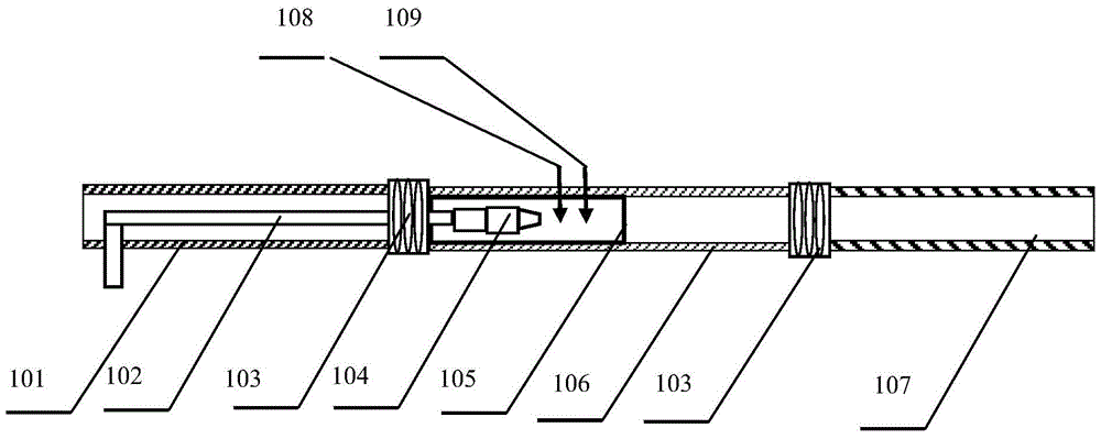
[0030] refer to figure 1 , the radiant pyrolysis tube of this embodiment includes a straight gas radiant tube, along the axial direction, the first radiant tube 101 is a cooling section for cooling semi-coke preheated air and gas, and the second radiant tube 106 is a gas-fired In the heating section, the third radiant tube 107 is used for flue gas cooling, and is used for preheating and drying pulverized coal raw materials to form a preheating section.

[0031] A gas burner, an electronic igniter 108 and a fire detection probe 109 are installed in the second radiant tube 106 . The gas delivery pipe 102 passes through the first radiant pipe 101 and enters the second radiant pipe 106 , and is connected with the gas burner 104 .

[0032] Among them: the preheating section adopts ordinary carbon steel pipe; the heating section adopts high temperature resistant stainless steel pipe (310S material) with silicon carbide lining 105 inside; the cooling section adopts ordinary carbon s...

Embodiment 2

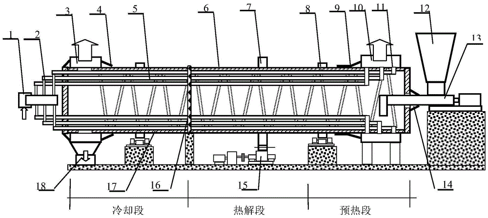
[0034] combine Figure 1-Figure 3 The structure of the rotary furnace device provided in this embodiment includes: raw coal bunker 12, rotary furnace body 6, rotary furnace body 6 is driven by transmission gear 7, wheel belt 8 and main transmission device 15, rotary furnace body 6 is provided with heat Gas outlet 3, flue gas outlet 10, furnace body insulation layer 17 and semi-coke outlet 18, the raw coal is transported into the rotary furnace body 6 through the pulverized coal conveying reamer 13, and the pulverized coal conveying reamer 13 and the rotary furnace body 6 pass through The feed sealing device 14 seals; the hot gas outlet 3 and the rotary furnace body are sealed and connected through the gas dynamic sealing device 4 .

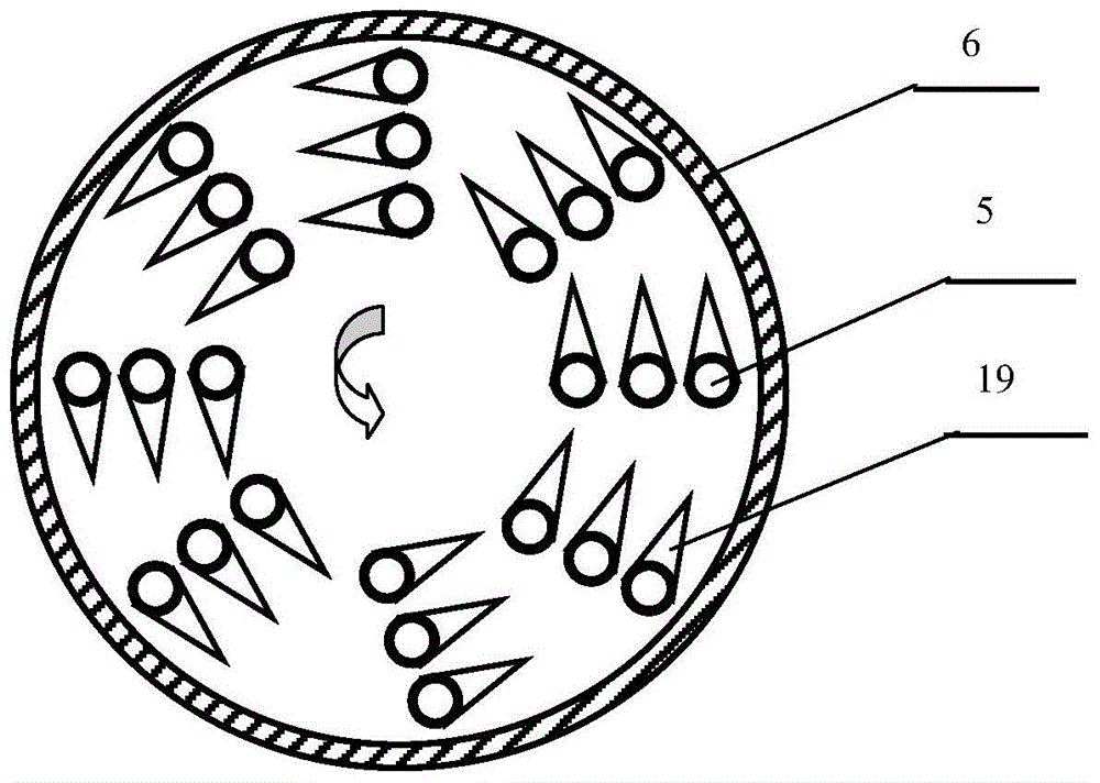
[0035] Radiation pyrolysis tubes 5 are arranged parallel to the axial direction of the rotary furnace body 6, forming an annular radiant tube layer in the radial section of the rotary furnace. Depending on the cross-sectional area of ​​the rotary ...


PUM

PropertyMeasurementUnit
diameteraaaaaaaaaa

Abstract

The invention relates to a radiation pyrolytic tube and a pulverized coal pyrolytic rotary furnace. The radiation pyrolytic tube comprises three radiation tubes which are sequentially connected, namely a first radiation tube, a second radiation tube and a third radiation tube, wherein a fuel gas nozzle and an igniter are arranged inside the second radiation tube; the pulverized coal pyrolytic rotary furnace comprises a rotary furnace body, wherein a plurality of radiation pyrolytic tubes are arranged inside the furnace body. By adopting the pulverized coal pyrolytic rotary furnace, the smoke afterheat is utilized for preheating and drying the raw coal and the carbocoal afterheat is utilized for preheating the combustion air and the coal gas; the heat utilization rate is high, the pulverized coal drying, preheating, pyrolysis and carbocoal cooling process are integrally designed and the pyrolytic process is simplified. The rotary furnace provided by the invention is large in heat exchange area, high in pulverized coal processing amount, simple in structure and suitable for million tons of pulverized coal large-scale pyrolytic production.

Description

technical field [0001] The invention relates to a device for pyrolysis of pulverized coal, in particular to a radiation pyrolysis tube and a rotary kiln for pyrolysis of pulverized coal. Background technique [0002] The existing pulverized coal pyrolysis rotary furnace has the problems of complex structure, high cost, small heat transfer area and low thermal efficiency. Contents of the invention [0003] In view of the defects or deficiencies in the prior art, one of the purposes of the present invention is to provide a radiation tube. [0004] The radiant pyrolysis tube provided by the present invention comprises three sections of radiant tubes connected in succession, which are respectively the first radiant tube, the second radiant tube and the third radiant tube, and the second radiant tube is provided with a gas burner and an ignition device. [0005] The gas burner is communicated with a gas delivery pipe, and the gas delivery pipe passes through the first radiant...

Claims


Application Information

Patent Timeline
Patent Type & Authority Patents(China)
IPC IPC(8): C10B53/04C10B15/00C10B47/30C10B39/00C10B57/10
CPCY02P20/129
Inventor 赵鹏冯雷姜国璋马飞高光耀
Owner CHANGAN UNIV
Why Eureka
Try Eureka