Electronic control beam scanning reflection array antenna and beam scanning method thereof

A reflect array antenna and beam scanning technology, applied to antennas, electrical components, etc., can solve the problems of inaccurate phase values, decreased stability, clumsiness, etc., and achieve the effects of reducing manufacturing costs, improving stability, and facilitating processing

Active Publication Date: 2015-07-15
UNIV OF ELECTRONICS SCI & TECH OF CHINA
View PDF4 Cites 23 Cited by
  • Summary
  • Abstract
  • Description
  • Claims
  • Application Information

AI Technical Summary

Problems solved by technology

[0004] In 1995, J.Huang et al. proposed for the first time the use of a microcomputer structure to adjust the rotation angle of the radiation patch to achieve changes in the front phase and beam scanning, but this method requires mechanical control, so the beam scanning response speed slow and clumsy
In 2006, M.R.Chaharmir et al. proposed an optically controlled electronic scanning reflectarray antenna, which controls the carrier concentration in the semiconductor by controlling the strength of the corresponding light source behind each unit, thereby changing the reflection phase value of the unit, but its control components High processing requirements, expensive dielectric materials, and inaccurate phase values ​​limi

Method used


Image

  • Electronic control beam scanning reflection array antenna and beam scanning method thereof
  • Electronic control beam scanning reflection array antenna and beam scanning method thereof
  • Electronic control beam scanning reflection array antenna and beam scanning method thereof

Examples


Embodiment

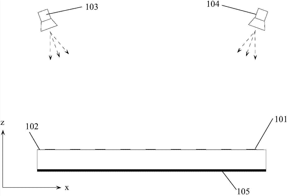
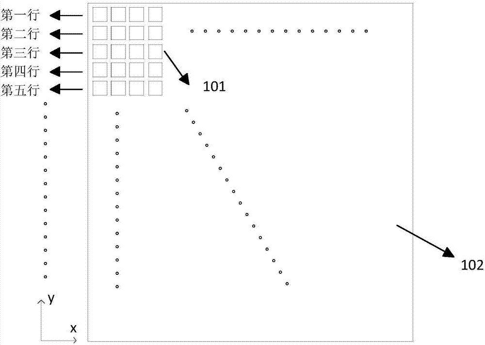
[0039] figure 1 , figure 2 It is an overall schematic diagram of the beam scanning reflectarray antenna of the present invention. The initial two feed sources 103, 104 irradiate the surface 102, and the planar array 102 is formed by many microstrip units 101 of different sizes to compensate for the spatial phase difference, thereby realizing the focusing of the beam . The phase distribution on the array is formed by the superposition of the electric fields generated by 103 and 104 , and the phase distribution on the array can be changed by changing the excitation amplitude ratio of the feed sources 103 and 104 , so as to realize beam scanning. In this specific implementation example, the number of array elements is 3×10.

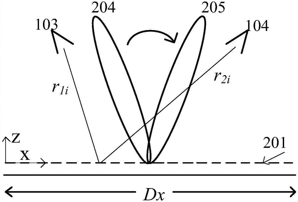
[0040] image 3 It is a side view of the array antenna of the specific implementation example of the present invention, the length DX of the array surface 201 along the x-axis direction is 120mm, the position of the feed source 103 is x=48mm, z=120mm, y=...


PUM

PropertyMeasurementUnit
Thicknessaaaaaaaaaa

Abstract

The invention discloses an electronic control beam scanning reflection array antenna and a beam scanning method thereof. The antenna is low in cost and loss and simple in structure. The antenna is characterized in that two initial feed sources are adopted in the antenna to perform irradiation excitation on a reflective array plane, and the excitation amplitude ratio of the feed source 1 to the feed source 2 is changed to change the phase value distribution of a total incident field in the array plane so that electronic control beam scanning can be achieved. The antenna is simple in structure and does not need extra biasing circuits, so that machining is convenient, and stability is high. High-gain beam scanning can be achieved just through the two initial feed sources without extra T/R modules, so that the manufacturing cost is effectively lowered. The antenna is suitable for microwave or millimeter wave or terahertz frequency bands and can be used in wireless communication and radar systems.

Description

technical field [0001] The invention belongs to the fields of wireless communication technology, radar technology and imaging technology, and in particular relates to an electronically controlled beam scanning array antenna and a beam scanning method that can effectively reduce costs. Background technique [0002] Array antennas with beam scanning play an increasingly important role in modern wireless communication technology, radar systems and imaging. Traditional phased array antennas can independently control the amplitude and phase of each unit in the array, so that beam forming and scanning can be performed quickly and flexibly, and it has unique advantages such as multi-target search and high-speed tracking. important position in the field. But for an array with a large number of elements, a large number of transceiver components and a complex feed network are necessarily required, which means expensive manufacturing costs, awkward weight and high loss. These shortco...

Claims


Application Information

Patent Timeline
IPC IPC(8): H01Q3/44H01Q15/14H01Q19/10
Inventor 屈世伟吴伟伟易欢陈龙杨仕文聂在平
Owner UNIV OF ELECTRONICS SCI & TECH OF CHINA
Why Eureka
Try Eureka