
Control circuit and control method of vehicle-mounted charger DC-DC system

A technology of DC-DC and on-board charger, which is applied in the direction of battery circuit devices, current collectors, circuit devices, etc., can solve the problems of charging system safety impact, high inductance current, damage to chips, etc., to achieve easy process implementation and reduce chip costs , The effect of simple circuit function principle

Active Publication Date: 2015-07-15
南京国博电子股份有限公司
View PDF4 Cites 7 Cited by
  • Summary
  • Abstract
  • Description
  • Claims
  • Application Information

AI Technical Summary

Problems solved by technology

Second, in the constant current charging stage, the system may continuously output a charging current of 1A-3A for different types of loads
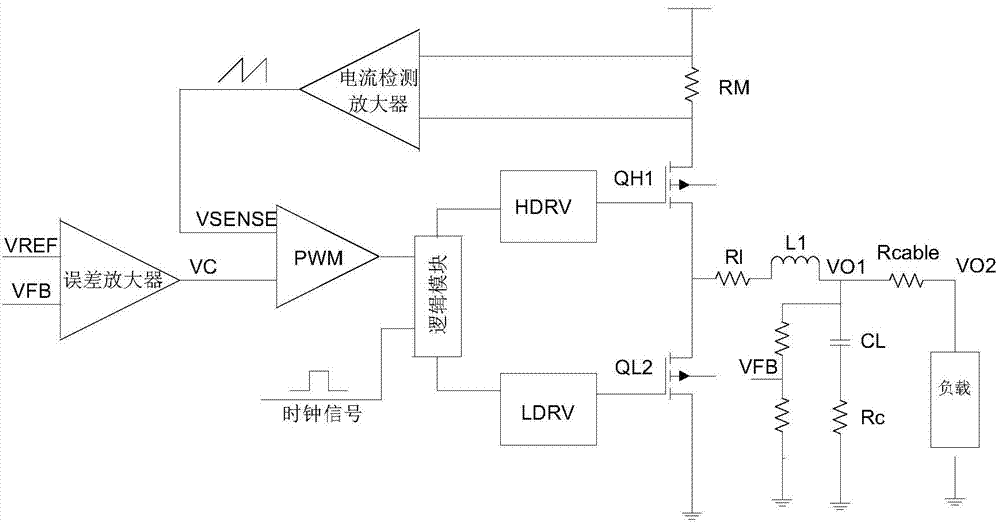
while in figure 1 It can be seen that there is a line resistance of about Rcable=150mΩ between the DC-DC output terminal and the actual load. If the output current is 2A, the voltage drop on this resistance will reach 300mV, which will affect the charged system. Safety is affected, so the car charger DC-DC needs to add line voltage loss compensation function
Third, if the system output is mistakenly short-circuited to ground, it will cause a large current in the inductor. Therefore, it is necessary to add a peak current limiting function to prevent damage to the chip due to large current conduction.

Method used


Image

  • Control circuit and control method of vehicle-mounted charger DC-DC system
  • Control circuit and control method of vehicle-mounted charger DC-DC system
  • Control circuit and control method of vehicle-mounted charger DC-DC system

Examples


Embodiment Construction

[0023] The specific embodiments of the present invention will be further described below in conjunction with the accompanying drawings.

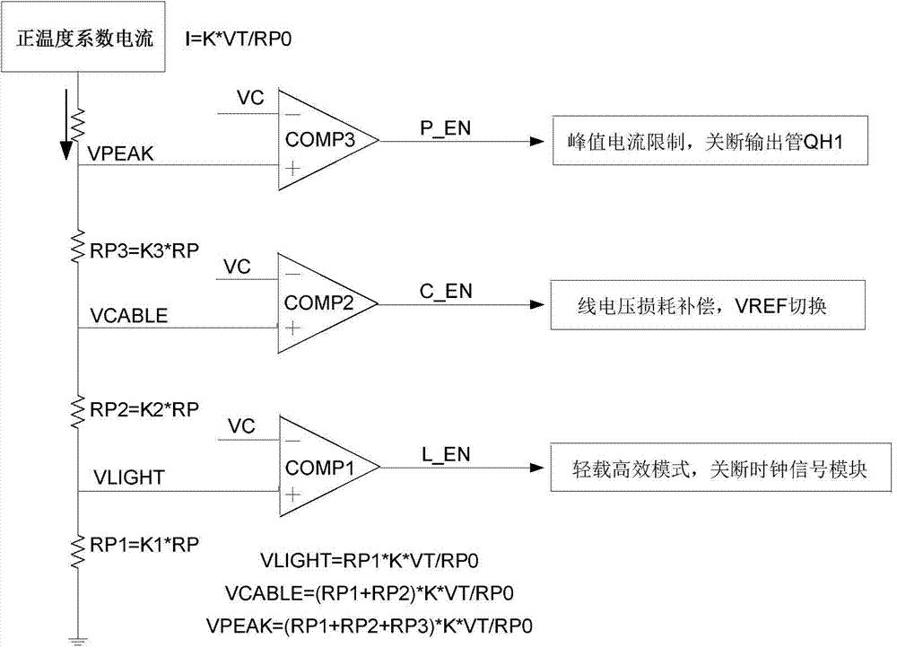
[0024] Such as figure 1 As shown, the current sense amplifier detects the voltage drop of the metal parasitic resistance RM on the power tube path and amplifies it, and the output of the current sense amplifier is the amplified voltage signal VSENSE, which has the same temperature coefficient as the metal resistance RM, about 3000ppm , this VSENSE signal will be compared with the output signal VC of the internal error amplifier through the PWM comparator to control the change of the output duty cycle. When VSENSE reaches VC in each cycle, the power tube will be turned off and wait for the next clock signal to come. Turn on the power tube, and so on. figure 2 The curve shows the relationship between VSENSE and VC signal, so that the peak value of VSENSE signal in each cycle will be equal to VC, so the VC signal will have the same variation ...


PUM


Abstract

The invention discloses a control circuit and a control method of a vehicle-mounted charger DC-DC system. The control method comprises the following steps: using a light-load comparator, a line loss compensation comparator and a peak current limit comparator, connecting negative input ends of the three comparators with an output signal of an error amplifier inside the DC-DC system, and connecting the positive input ends with voltages with different values, which are formed on serially-connected polysilicon resistors by positive temperature coefficient current output by a positive temperature coefficient current generating module; outputting light-load high-efficiency mode, line loss voltage compensation and peak current limit control signals at an output end. Through the control method, output current can be monitored, light-load high-efficiency mode, line loss compensation and peak current limit threshold values are determined, and the threshold values do not change along with the temperature; the control circuit is simple in functional principle and easy in process realization, can reduce the cost of a chip, is high in reliability, and is applicable to other DC-DC systems needing such functions.

Description

technical field [0001] The invention relates to a DC-DC system applied to a car charger, and realizes light-load high-efficiency, line The technology of loss voltage compensation and peak current limit control belongs to the technical field of DC-DC converter. Background technique [0002] With the vigorous development of portable electronic products, DC-DC converters have been widely used in electronic products, the market prospect is very broad, and the requirements for their performance are getting higher and higher, such as input and output voltage range, output maximum current , power conversion efficiency, operating frequency and power volume. [0003] On-board charger is a relatively new application field of DC-DC. This kind of DC-DC belongs to the BUCK type voltage converter, which has a high voltage application range and requires high light-load conversion efficiency. The cable of the battery is long, and there will be a large voltage loss when outputting a large ...

Claims


Application Information

Patent Timeline
Patent Type & Authority Applications(China)
IPC IPC(8): H02M3/155H02J7/00
Inventor 康明辉朱波郭玮
Owner 南京国博电子股份有限公司
Learn More