Manufacturing method for nickel-copper end sockets

A nickel-copper alloy and manufacturing method technology, applied in the field of nickel-copper alloy head manufacturing, can solve the problems that the workpiece cannot meet technical requirements, difficult forming and processing, poor plastic deformation, etc., and achieve reasonable distribution of metal streamlines and thermal processing system. Feasible, stable performance

Inactive Publication Date: 2015-07-22
无锡市前洲西塘锻压有限公司
View PDF6 Cites 3 Cited by
  • Summary
  • Abstract
  • Description
  • Claims
  • Application Information

AI Technical Summary

Problems solved by technology

Due to the disadvantages of poor plastic deformation, easy cracking, and large resilience during cold forming of nickel-copper alloys, it is difficult to form and process. If the method is improper or the process is unreasonable, the workpiece cannot meet the technical requirements and the forming is difficult. It is easy to cause problems such as tearing during forming, resulting in scrapping

Method used


Image

  • Manufacturing method for nickel-copper end sockets
  • Manufacturing method for nickel-copper end sockets
  • Manufacturing method for nickel-copper end sockets

Examples


Embodiment 1

[0024] The present invention is applied to the NCu30 nickel-copper alloy plate head of ¢1100 / 30mm specification, and the specific implementation method is as follows:

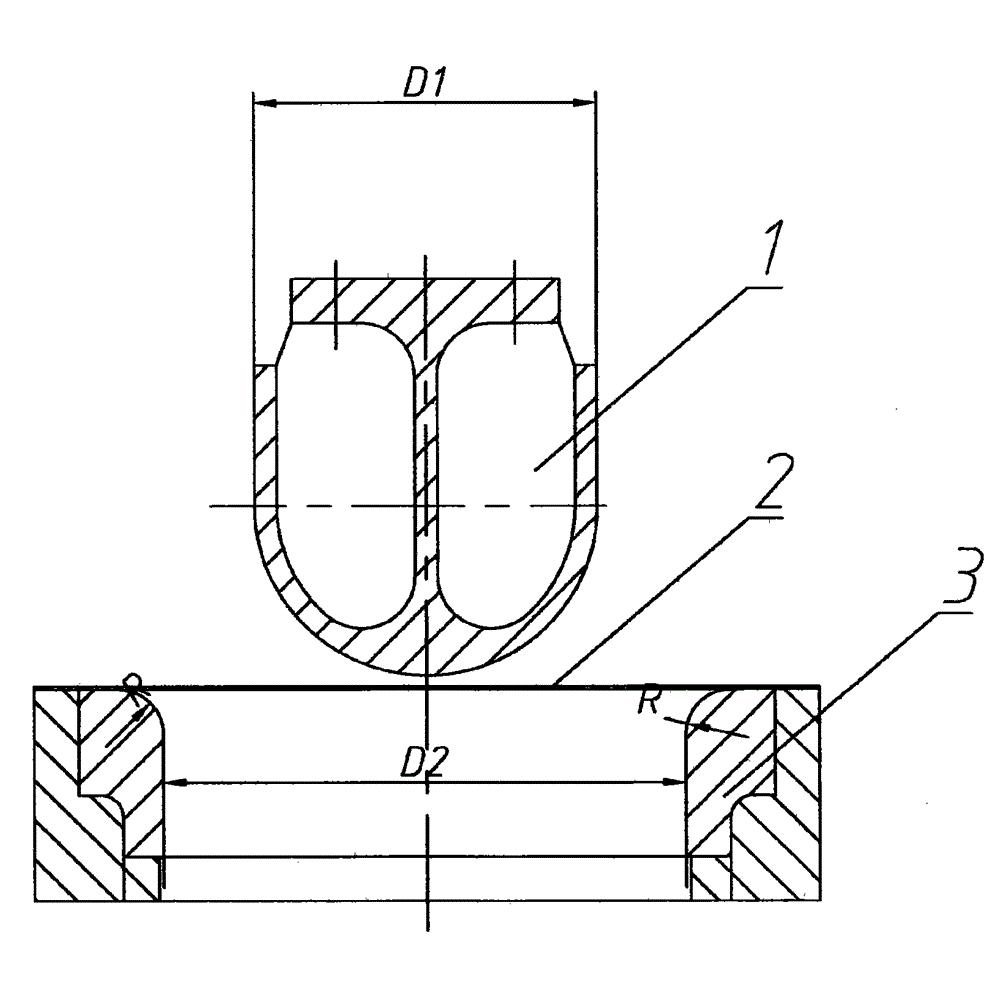
[0025] (1), mold design: the diameter of the head is 1100mm, the wall thickness is 30mm, and the diameter D of the upper mold pressure head is calculated according to the formula of the technical plan 1 Take 1106mm, the diameter of the outlet of the lower die pull ring is D 2 Take 1170mm, take the gap Z between the upper and lower molds as 31.8mm, and take the fillet R of the lower mold pull ring as 75mm;

[0026] (2), mold grinding and cleaning: before pressing, the mold is polished and cleaned;

[0027] (3) Pre-treatment of the billet: grinding and cleaning the edge of the billet to remove oxidation and peripheral burrs generated during flame cutting around the billet; before stamping the billet, the edge of the surface is beveled, the beveling angle is 4°, and the edge is cut off at most The thickness is 3...

Embodiment 2

[0042] The present invention is applied to the NCu30 nickel-copper alloy plate head of ¢2400 / 30mm specification, and the specific implementation method is as follows:

[0043] (1) Mold design: the diameter of the head is 2400mm, the wall thickness is 30mm, and the diameter D of the upper mold head is calculated according to the formula of the technical plan 1 Take 2417mm, the diameter of the outlet of the lower die pull ring is D 2 Take 2481mm, take the gap Z between the upper and lower molds as 31.8mm, and take the fillet R of the lower mold pull ring as 105mm;

[0044] (2), mold grinding and cleaning: before pressing, the mold is polished and cleaned;

[0045] (3) Pre-treatment of the billet: grinding and cleaning the edge of the billet to remove oxidation and peripheral burrs generated during flame cutting around the billet; before stamping the billet, the edge of the surface is beveled, the beveling angle is 5°, and the edge is cut off at most The thickness is 3mm; befor...

Embodiment 3

[0055] The present invention is applied to the NCu30 nickel-copper alloy plate head of ¢1800 / 30mm specification, and the specific implementation method is as follows:

[0056] (1), mold design: the diameter of the head is 1800mm, the wall thickness is 30mm, and the diameter D of the upper mold pressure head is calculated according to the formula of the technical plan 1 Take 1811mm, the diameter of the outlet of the lower die pull ring is D 2 Take 1875mm, the gap Z between the upper and lower molds is 31.8mm, and the rounded corner R of the lower mold pull ring is 90mm;

[0057] (2), mold grinding and cleaning: before pressing, the mold is polished and cleaned;

[0058] (3) Pre-processing of the billet: grinding and cleaning the edge of the billet to remove oxidation and peripheral burrs generated during flame cutting around the billet; before stamping the billet, the edge of the surface is beveled, the beveling angle is 4.5°, and the edge is cut off at most The thickness is ...


PUM


Abstract

The invention relates to a metal material machining technology and manufacturing method, in particular to a manufacturing method for nickel-copper end sockets. The manufacturing method comprises the steps of designing a die; calculating the diameter of an upper die pressure head, the diameter of an outlet of a lower die pull ring, the gap between an upper die and a lower die and the circular bead of the lower die pull ring; polishing and cleaning the die; carrying out earlier stage processing of blanks; carrying out heating through a natural gas furnace; carrying out stamping forming, wherein three-time forming is adopted for the forming technology; carrying out spinning forming; cutting grooves; carrying out acid dipping; carrying out polishing; carrying out penetrant flaw detection; stacking the end sockets. By means of the method, the stamping process is stable, transformation is even and smooth, a determined hot working system is feasible, the technology parameters are reasonable, control over the dimension of workpieces is good, metal streamline distribution is reasonable, and performance is stable.

Description

technical field [0001] The invention relates to a manufacturing method of metal material processing technology, in particular to a manufacturing method of a nickel-copper alloy head. Background technique [0002] Nickel-copper alloy is an excellent engineering structure material. With the expansion of its usage year by year, it is more and more used in the processing and manufacturing of various engineering structures and equipment. Due to the disadvantages of poor plastic deformation, easy cracking, and large resilience during cold forming of nickel-copper alloys, it is difficult to form and process. If the method is improper or the process is unreasonable, the workpiece cannot meet the technical requirements and the forming is difficult. It is easy to cause problems such as tearing during forming, resulting in scrapping. Contents of the invention [0003] The purpose of the present invention is to overcome the deficiencies in the prior art, thereby providing a manufactu...

Claims


Application Information

Patent Timeline
Patent Type & Authority Applications(China)
IPC IPC(8): B23P15/00
CPCB23P15/00
Inventor 刘熹顾蔚枫唐国强潘长标
Owner 无锡市前洲西塘锻压有限公司
Why Eureka
Try Eureka