Multi-layer parallel-connection overlaid frame type spraying flue gas waste heat recovery and heat exchange device

A flue gas waste heat and heat exchange device technology, applied in direct contact heat exchangers, heat exchanger types, water shower coolers, etc. Thermal effect and other issues, to achieve the effect of reducing the operating cost of the device, facilitating the monitoring of equipment quality, and reducing the amount of flue gas treatment

Active Publication Date: 2015-07-22
TSINGHUA UNIV +1
View PDF5 Cites 2 Cited by
  • Summary
  • Abstract
  • Description
  • Claims
  • Application Information

AI Technical Summary

Problems solved by technology

The use of a partitioned heat exchange device is beneficial to ensure the quality of circulating water, but the heat transfer effect of the partitioned heat exchange device is poor, and the pipelines of the heat exchange equipment are large, complex and occupy a large area. Scale blockage will affect the heat exchange effect and increase the burden of maintenance and cleaning in the later period, resulting in shortened service life of the device
In the spray contact flue gas-water heat exchange device, in order to increase the air-water contact area, the cooling water needs to be fine mis...

Method used


Image

  • Multi-layer parallel-connection overlaid frame type spraying flue gas waste heat recovery and heat exchange device
  • Multi-layer parallel-connection overlaid frame type spraying flue gas waste heat recovery and heat exchange device
  • Multi-layer parallel-connection overlaid frame type spraying flue gas waste heat recovery and heat exchange device

Examples


Embodiment 1

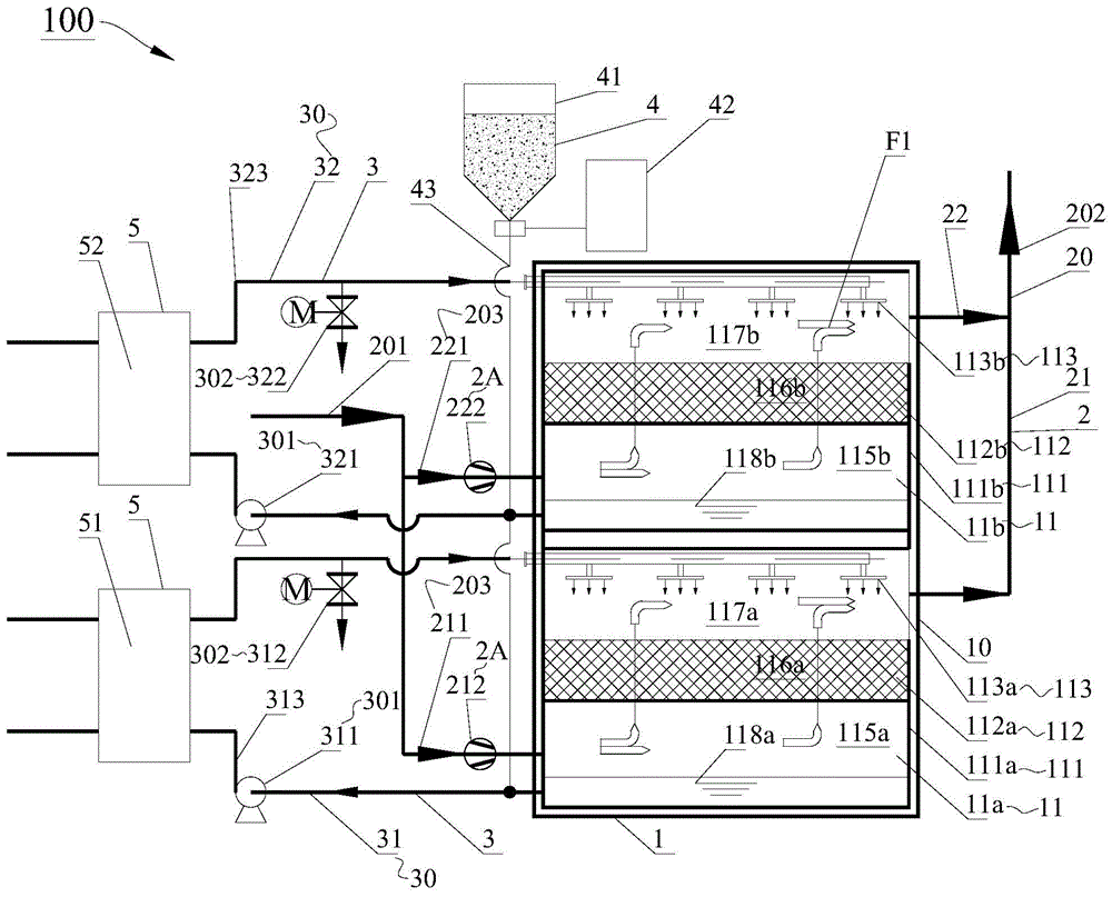
[0076] In the first embodiment, if Figure 1-Figure 6 As shown, the flue gas waste heat recovery heat exchange tower 1 includes the first spray flue gas waste heat recovery heat exchange assembly 11a and the second spray flue gas waste heat recovery heat exchange assembly 11b, and the second spray flue gas waste heat recovery heat exchange assembly 11b. The heat component 11b is located above the heat exchange component 11a for recovery of waste heat from spraying flue gas on the first layer, and the two are supported and connected as a whole by the frame structure 10 of the heat exchange tower.

[0077] In Embodiment 1, the branch flue system 203 of the multi-layer stacked parallel flue gas system 2 includes the first layer branch flue system 21 and the second layer branch flue system 22 to respectively connect the waste heat of the first layer spraying flue gas The recovery heat exchange component 11a and the second layer spray flue gas waste heat recovery heat exchange comp...

Embodiment 2

[0097] In the second embodiment, if Figure 7-Figure 8 As shown, the structure of the multi-layer parallel stacked frame type shower flue gas waste heat recovery heat exchange device 100 in Embodiment 2 is substantially the same as that of the first embodiment. I won't go into details here.

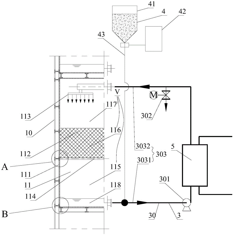
[0098] The difference is that in the second embodiment, as Figure 7 As shown, one end of the alkali addition pipeline system 43 of the alkali addition neutralization system 4 is connected to the alkali addition storage tank 41, and the other end of the alkali addition pipeline system 43 is respectively connected to a plurality of spray flue gas waste heat recovery heat exchange components 11. The accommodating spaces V are connected, that is to say, the alkaline neutralization system 4 directly puts alkaline substances into the accommodating spaces V of the corresponding spray flue gas waste heat recovery heat exchange components 11 to neutralize the spray water.

[0099] In the second...

Embodiment 3

[0106] In the third embodiment, such as Figure 9 As shown, the structure of the multi-layer parallel stacked frame type shower flue gas waste heat recovery heat exchange device 100 in Embodiment 3 is basically the same as that of the embodiment 1. I won't go into details here.

[0107] The difference is that in Example 1, as figure 1 As shown, the fan 2A of the multi-layer stacked parallel flue gas system 2 is connected in series to the inlet main flue 201, and the fan 2A is arranged before the flue gas waste heat recovery heat exchange tower 1, that is, the flue gas conveying fan in Embodiment 1 is driven by the front Way.

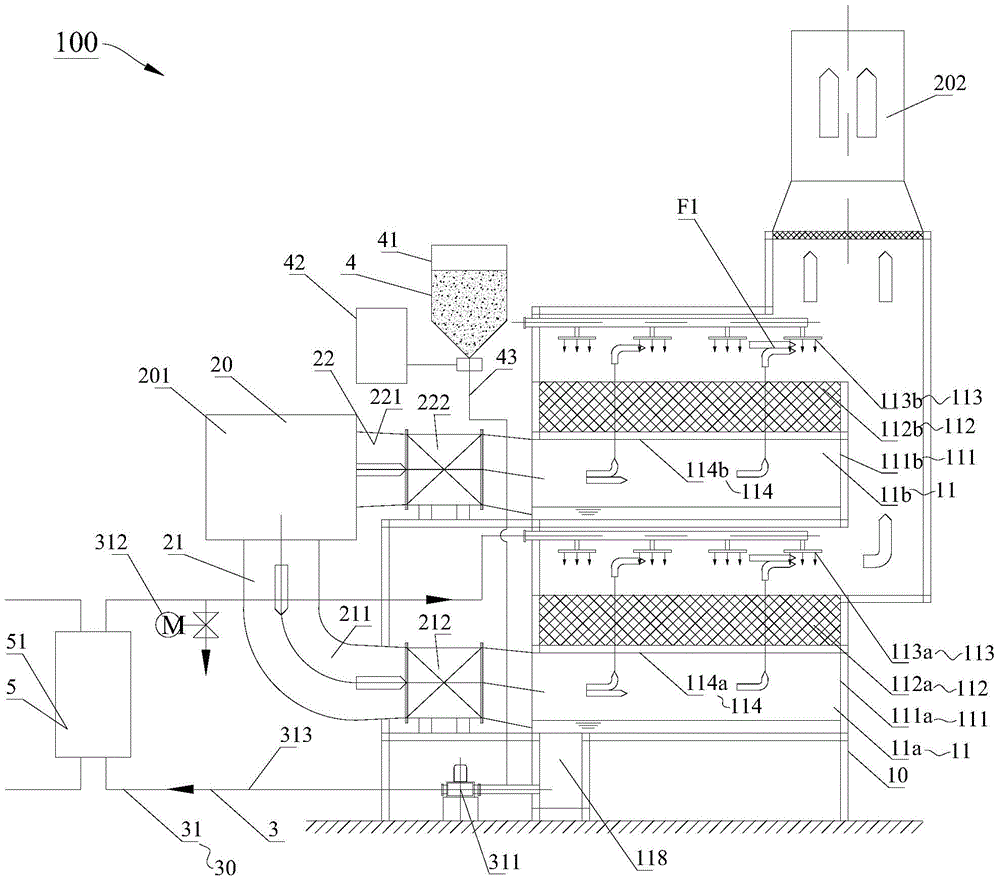
[0108] And in embodiment three, if Figure 9 As shown, the multi-layer stacked parallel flue gas system 2 also includes a fan 2A, which is connected in series to the outlet main flue 202, and the fan 2A is arranged behind the flue gas waste heat recovery heat exchange tower 1, that is, the flue gas transportation of the third embodiment The fan adopt...


PUM


Abstract

The invention discloses a multi-layer parallel-connection overlaid frame type spraying flue gas waste heat recovery and heat exchange device. The device comprises a flue gas waste heat recovery and heat exchange tower, a multi-layer overlaid parallel-connection flue gas system, a multi-layer overlaid spraying and delivering loop system, an alkaline adding neutralization system and a waste great recovery heat energy utilizing system. A plurality of overlaid spraying flue gas waste heat recovery and heat exchange assemblies are arranged in the flue gas waste heat recovery and heat exchange tower, supported and connected into a whole through a heat exchanger tower frame structure and connected in parallel on a flue gas circulating loop. According to the multi-layer parallel-connection overlaid frame type spraying flue gas waste heat recovery and heat exchange device, the heat exchange performance of the device is remarkably enhanced, and recovered waste heat can be increased by 20-40%; flue gas flowing resistance and the power consumption of a draught fan are remarkably reduced, all the spraying flue gas waste heat recovery and heat exchange assemblies can independently run, and running is more economical and more flexible; the acidoid absorbing performance can also be remarkably improved, and therefore the desulfurization and denitration dust removal effects of flue gas can be greatly enhanced; meanwhile, the occupied area can also be remarkably reduced, cost of investment is saved, the quality of equipment can be monitored conveniently, and potential safety hazards of site construction are reduced.

Description

technical field [0001] The invention relates to the field of flue gas waste heat recovery equipment, in particular to a multi-layer parallel stacked frame type spray flue gas waste heat recovery heat exchange device. Background technique [0002] The deep recovery and utilization of waste heat of flue gas can obtain significant energy saving and environmental protection benefits. At present, the flue gas waste heat recovery devices of large boilers generally adopt partition wall heat exchange devices with fins or spray contact heat exchange devices. In the partition wall heat exchange device, the cooling circulating water and the flue gas are separated by a solid wall, and the heat of the flue gas is transferred to the cooling circulating water through the solid wall. The use of a partitioned heat exchange device is beneficial to ensure the quality of circulating water, but the heat transfer effect of the partitioned heat exchange device is poor, and the pipelines of the he...

Claims


Application Information

Patent Timeline
IPC IPC(8): F23J15/04F23J15/06F28C1/00F28F25/06
CPCY02E20/30
Inventor 孟继安朱晓磊隋晓峰赵岩
Owner TSINGHUA UNIV
Why Eureka
Try Eureka