Pulsating heat pipe heat exchanger with lyophilic coatings

A technology of pulsating heat pipes and heat exchangers, which is applied to indirect heat exchangers, lighting and heating equipment, etc., can solve the problems of the working fluid and the inner wall of the pipeline without adopting enhanced heat exchange methods, so as to improve the temperature distribution characteristics and improve the heat transfer rate. The effect of high heat coefficient and heat transfer coefficient

Inactive Publication Date: 2015-07-22
ZHEJIANG UNIV
View PDF14 Cites 12 Cited by
  • Summary
  • Abstract
  • Description
  • Claims
  • Application Information

AI Technical Summary

Problems solved by technology

Although this invention can promote the circulating flow of the working fluid inside the pipeline to a certain extent, it does not adopt enhanced heat exchange means for the heat exchange process between the working fluid and the inner wall of the pipeline, which is obviously different from the present invention.

Method used


Image

  • Pulsating heat pipe heat exchanger with lyophilic coatings
  • Pulsating heat pipe heat exchanger with lyophilic coatings
  • Pulsating heat pipe heat exchanger with lyophilic coatings

Examples


Embodiment 1

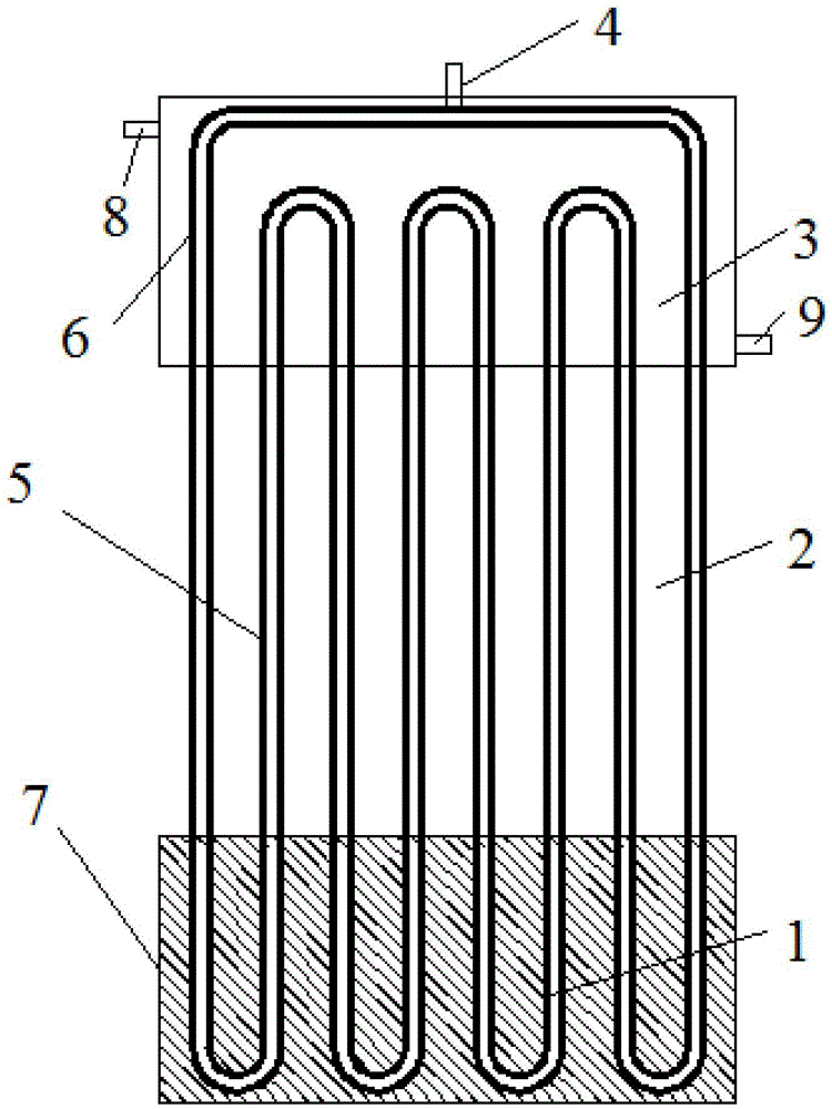
[0033] With the rapid development of the electronics industry, the physical size of electronic components is getting smaller and smaller, but their heat generation is getting bigger and bigger, which leads to an increasing heat flux density for heat dissipation. Therefore, traditional heat dissipation methods are facing huge challenge. This embodiment is mainly used to illustrate the application of a pulsating heat pipe with a lyophilic coating proposed by the present invention in the field of electronic heat dissipation.

[0034] as attached figure 2 As shown, a pulsating heat pipe with a lyophilic coating proposed by the present invention is connected to the heat sink plate 7 of the heat-generating electronic component through heat-conducting silicone grease. The calorific value of the electronic components is transferred to the evaporation section 1 of the pulsating heat pipe pipe 6 through the heat-conducting silicone grease and the heat sink plate 7. The adjacent gas o...

Embodiment 2

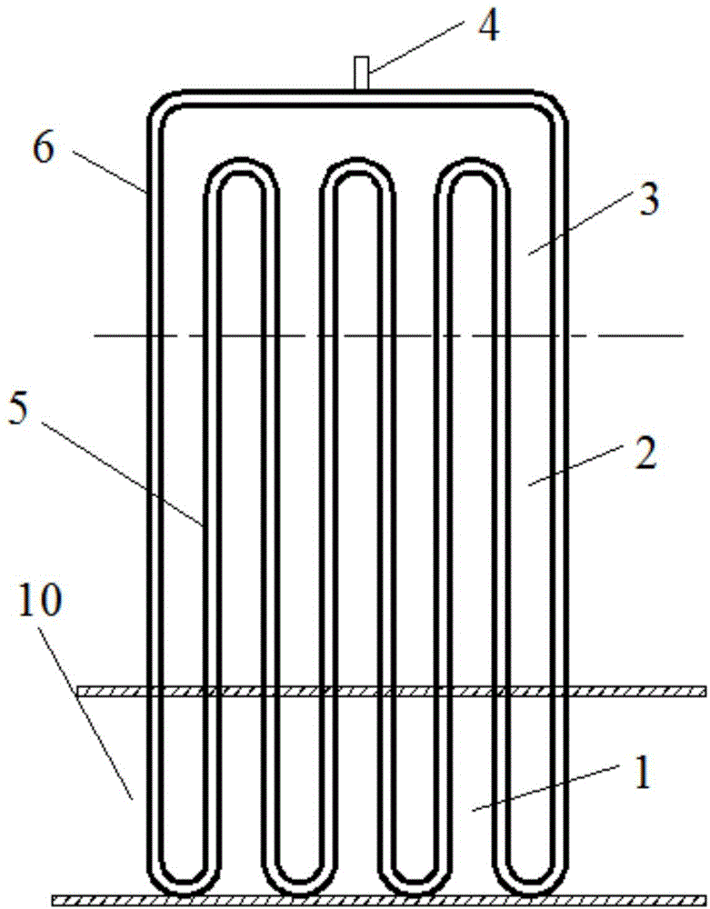
[0045] Due to the inevitable waste of energy in industrial production, most of this energy is lost in the form of heat energy. Recovering this part of energy is of great significance for improving the energy utilization efficiency of industrial production. This embodiment is mainly used to illustrate the application of a pulsating heat pipe with a lyophilic coating inside in the field of industrial waste heat recovery proposed by the present invention.

[0046] as attached image 3 As shown, the evaporating section 1 of a pulsating heat pipe with a lyophilic coating inside proposed by the present invention is placed in an industrial waste heat pipeline 10, while the condensing section 3 is arranged in an environment where we need to utilize waste heat. Since the pipe diameter of the pulsating heat pipe is small, when the inside of the pulsating heat pipe is filled with working fluid, a state of alternate existence of gas plugs and liquid plugs will be formed inside the pulsati...


PUM


Abstract

The invention discloses a pulsating heat pipe heat exchanger with lyophilic coatings. The pulsating heat pipe heat exchanger comprises an evaporating segment, a heat insulation segment and a condensation segment which are connected in sequence, and the evaporating segment, the heat insulation segment and the condensation segment are filled with heat exchange working media. The pulsating heat pipe heat exchanger is characterized in that the inner wall of the evaporating segment, the inner wall of the heat insulation segment and the inner wall of the condensation segment are coated with the lyophilic coatings corresponding to the heat exchange working media. The lyophilic coating is arranged on the inner wall of a pulsating heat pipe, the thickness and materials of the coatings correspond to the type of the working media injected into the pulsating heat pipe, and therefore the working media can be spread out on the surfaces of the materials well. Due to the lyophilic coatings, the heat exchange process of the liquid phase working media and the wall of the pipe is greatly enhanced, the heat transfer performance of the pulsating heat pipe can be effectively improved, the temperature difference of the evaporating segment and the condensation segment of the pulsating heat pipe is reduced, the work occasion of the pulsating heat pipe heat exchanger is further widened, and the pulsating heat pipe heat exchanger has very good application prospects.

Description

technical field [0001] The invention belongs to the field of heat exchange, in particular to a pulsating heat pipe heat exchanger with a lyophilic coating. Background technique [0002] In recent years, with the wide application of computers in scientific research and engineering fields, the electronics industry has entered a period of rapid development, and the processing technology of processors has become more and more advanced. The data that the CPU can process and the speed of operation are getting faster and faster, and the degree of integration is getting higher and higher. Electronic products, especially high-tech products, are constantly developing towards high-density packaging and multi-functionalization. The miniaturization and high integration of electronic devices have become the trend of technological development. At the same time, the calorific value of electronic components is also increasing, which puts forward great requirements on the means of heat dissi...

Claims


Application Information

Patent Timeline
Patent Type & Authority Applications(China)
IPC IPC(8): F28D15/02
CPCF28D15/0266
Inventor 韩晓红王学会乔晓刚鹿丁王勤陈光明
Owner ZHEJIANG UNIV
Why Eureka
Try Eureka