Methanol-to-olefin reaction device

A methanol-to-olefins and reaction equipment technology, which is applied in coal-to-olefins and petrochemical fields, can solve problems such as lower yield and conversion rate of target products, uneven distribution of gas-solid, back-mixing of gas-solid two-phase, etc., and achieve improved contact Effect, reduce the concentration of fine powder particles, reduce the effect of residence time

Active Publication Date: 2015-07-29
CHINA UNIV OF PETROLEUM (BEIJING)
View PDF5 Cites 5 Cited by
  • Summary
  • Abstract
  • Description
  • Claims
  • Application Information

AI Technical Summary

Problems solved by technology

However, due to the uneven distribution of gas and solid in the dense-phase fluidized bed, the serious problem of gas-solid two-phase back-mixing will also lead to the generation of by-products, and the reduction of the yield and conversion rate of the target product

Method used


Image

  • Methanol-to-olefin reaction device
  • Methanol-to-olefin reaction device
  • Methanol-to-olefin reaction device

Examples


Embodiment 1

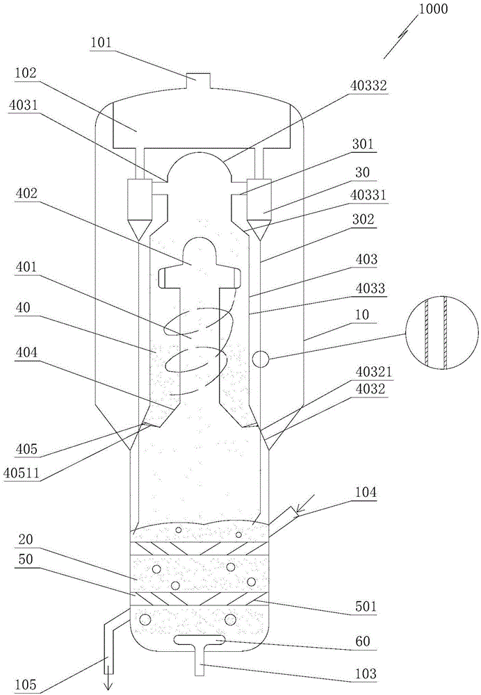
[0032] As a preferred embodiment of this embodiment, such as figure 1 As shown, the bottom of the outer cover 403 is provided with a second conical section 4032 that penetrates up and down. The diameter of the second conical section 4032 tapers upwards. The bottom of the second conical section 4032 constitutes the bottom of the gas-solid separation device 40. The second conical section The outside of the bottom of 4032 is in sealing connection with the inner wall of the housing 10, the first tapered section 404 is located inside the second tapered section 4032, and the bottom of the first tapered section 404 is connected to the inside of the second tapered section 4032 through an annular plate 405, as Figure 4 As shown, the annular plate 405 is evenly provided with a plurality of slots 4051 in the circumferential direction; the side wall of the second tapered section 4032 is provided with a first through hole 40321, and the particle output pipe 302 is sealed and enters the den...

Embodiment 2

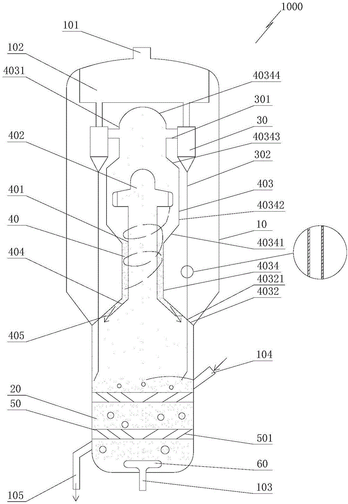
[0041] The basic principle and structure of this embodiment are the same as those of Embodiment 1, the difference lies in the structural form of the outer cover 403 and the one-way conduction way between the first conical section 404 and the dense-phase fluidized bed 20 from top to bottom.

[0042] Such as figure 2 As shown, in the second embodiment, the bottom of the outer cover 403 is provided with a second conical section 4032 that penetrates up and down. Bottom, the outside of the bottom of the second tapered section 4032 is in sealing connection with the inner wall of the housing 10, the first tapered section 404 is located inside the second tapered section 4032, and the bottom of the first tapered section 404 is connected to the second tapered section 405 through an annular plate 405. Shaped segment 4032 is connected inside, such as Figure 5 As shown, the annular plate 405 is evenly provided with a plurality of slots 4051; the side wall of the second tapered section 4...

Embodiment 3

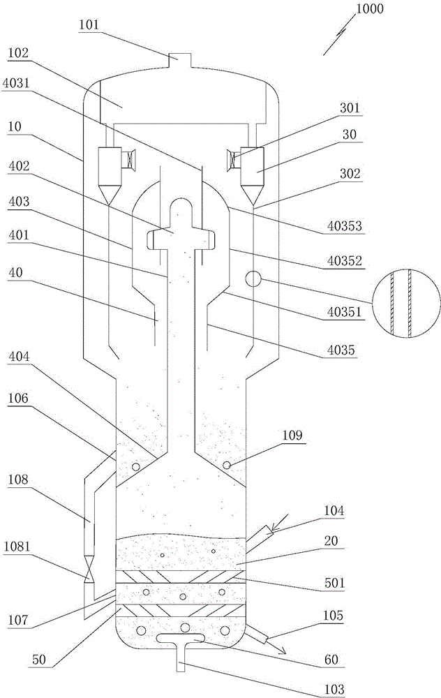
[0046] Such as image 3As shown, in the third embodiment, the bottom of the first conical section 404 constitutes the bottom of the gas-solid separation device 40, the outer side of the bottom of the first conical section 404 is in sealing connection with the inner wall of the housing 10, and the outer cover 403 includes the first conical section The fourth straight pipe 4035 arranged above 404, the quick separation device 402 is arranged above the inside of the fourth straight pipe 4035, the top of the fourth straight pipe 4035 is connected with a sixth tapered section 40351 whose diameter gradually expands upwards, and the sixth tapered section 40351 The top is connected with the fifth straight pipe 40352 , the top of the fifth straight pipe 40352 is connected with the third head 40353 , the top of the third head 40353 is provided with a first outlet 4031 , and the first outlet 4031 communicates with the first inlet pipe 301 . The outlet of the particle output pipe 302 is lo...


PUM

PropertyMeasurementUnit
heightaaaaaaaaaa

Abstract

The invention relates to a methanol-to-olefin reaction device which comprises a shell; a dense phase fluidized bed is arranged at the lower part of the inner side of the shell, and a produced gas outlet is formed in the top of the shell; an air chamber is arranged under the produced gas outlet; one or more cyclone separator(s) is/ are in through connection under the air chamber; the inner side of each cyclone separator is in through connection with a first inlet pipe along the tangential direction; the bottom of each cyclone separator is provided with a granule output pipe communicated with the dense phase fluidized bed; a gas-solid separation device is arranged at the upper part of the inner side of the shell; the gas-solid separation device is communicated with the first inlet pipe(s); grating plates are fixedly arranged in the dense phase fluidized bed along the transverse direction. After the methanol-to-olefin reaction device is used, the free space at the upper part of the reaction device is effectively reduced, the reaction time is shortened, and the operation conditions of the reaction device are closer to the best operation conditions, so that the selectivity of target products (ethylene and propylene) and the yield of olefin are improved, and the economic benefit of the device is improved; furthermore, the fine powder particle concentration in the gas at the inlet(s) of the cyclone separator(s) can be effectively reduced, and the service efficiency of a catalyst is improved.

Description

technical field [0001] The invention relates to the technical fields of coal-to-olefins and petrochemical industry, in particular to a methanol-to-olefins reaction equipment with a rapid separation structure for rapid export of output gas. Background technique [0002] Low-carbon olefins (ethylene and propylene, etc.) are the basic raw materials for petrochemicals. At present, ethylene is mainly produced by steam cracking of naphtha. Due to the shortage of petroleum resources, the cost of producing ethylene from naphtha is getting higher and higher. The ethylene production process with richer raw materials is being actively developed at home and abroad. Among them, the research on the production of ethylene and propylene from methanol has made substantial progress. [0003] The methanol-to-olefins reaction is a gas-solid heterogeneous catalytic reaction, using gas-solid fluidization technology. At present, industrial devices for producing light olefins from methanol use ...

Claims


Application Information

Patent Timeline
Patent Type & Authority Applications(China)
IPC IPC(8): B01J8/24C07C1/20C07C11/04C07C11/06
CPCY02P30/20Y02P30/40
Inventor 卢春喜崔刚刘梦溪王子健张永民
Owner CHINA UNIV OF PETROLEUM (BEIJING)
Why Eureka
Try Eureka