Multi-spindle numerical control vertical type special lathe

A CNC vertical and special-purpose lathe technology, which is applied in the field of mechanical processing, can solve problems such as the unification and improvement of machining accuracy of unfavorable parts, shorten the service life of CNC machine tools, and leakage of cooling water in chip removal mechanisms, so as to reduce equipment consumables and investment, The overall structure of the equipment is compact and stable, and the tool changing speed is fast.

Active Publication Date: 2015-07-29
JINAN FIRST MACHINE TOOL GROUP
View PDF7 Cites 4 Cited by
  • Summary
  • Abstract
  • Description
  • Claims
  • Application Information

AI Technical Summary

Problems solved by technology

[0003] At present, camshaft parts are processed by grinding, and single-spindle vertical or horizontal CNC lathes are usually used. Each CNC machine tool can only clamp one workpiece at a time, and each machine tool needs to be equipped with an operator. For mass production, It is not only inefficient but also a waste of human resources, which will increase the production cost of the enterprise and is not conducive to the unification and improvement of the machining accuracy of the parts
In addition, in the prior art, after long-term use of CNC lathes, the chip removal mechanism is prone to leakage of cooling water, which affects the environment, damages equipment, and shortens the service life of CNC lathes.

Method used


Image

  • Multi-spindle numerical control vertical type special lathe
  • Multi-spindle numerical control vertical type special lathe
  • Multi-spindle numerical control vertical type special lathe

Examples


Embodiment Construction

[0033] In order to make the purpose, technical solutions and advantages of the embodiments of the present invention clearer, the technical solutions in the embodiments of the present invention will be clearly and completely described below in conjunction with the drawings in the embodiments of the present invention. Obviously, the described embodiments It is a part of embodiments of the present invention, but not all embodiments. Based on the embodiments of the present invention, all other embodiments obtained by persons of ordinary skill in the art without creative efforts fall within the protection scope of the present invention.

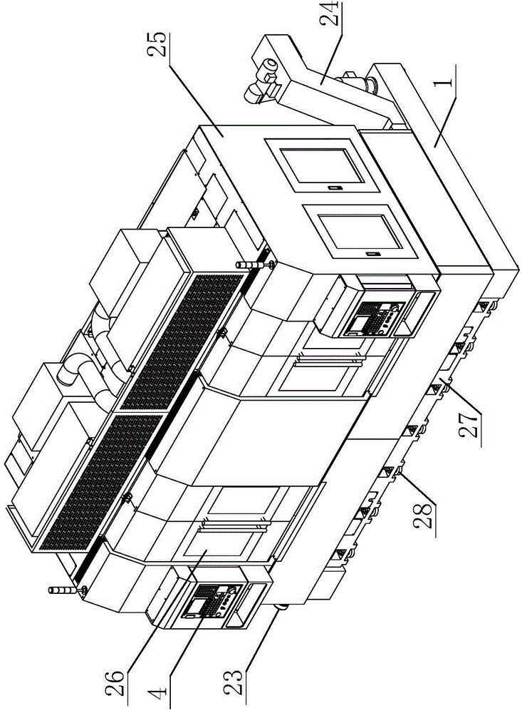
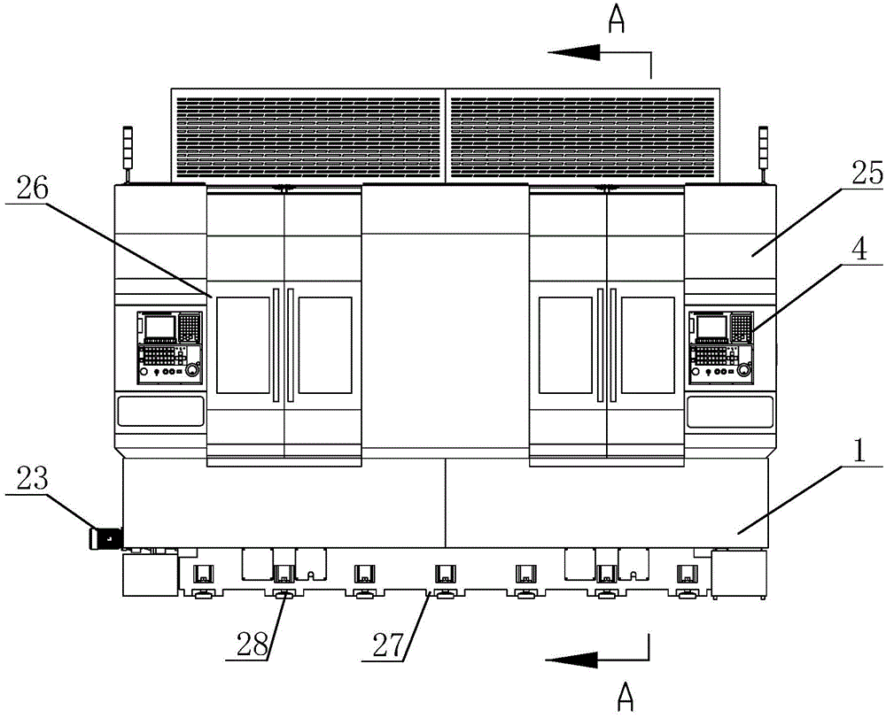
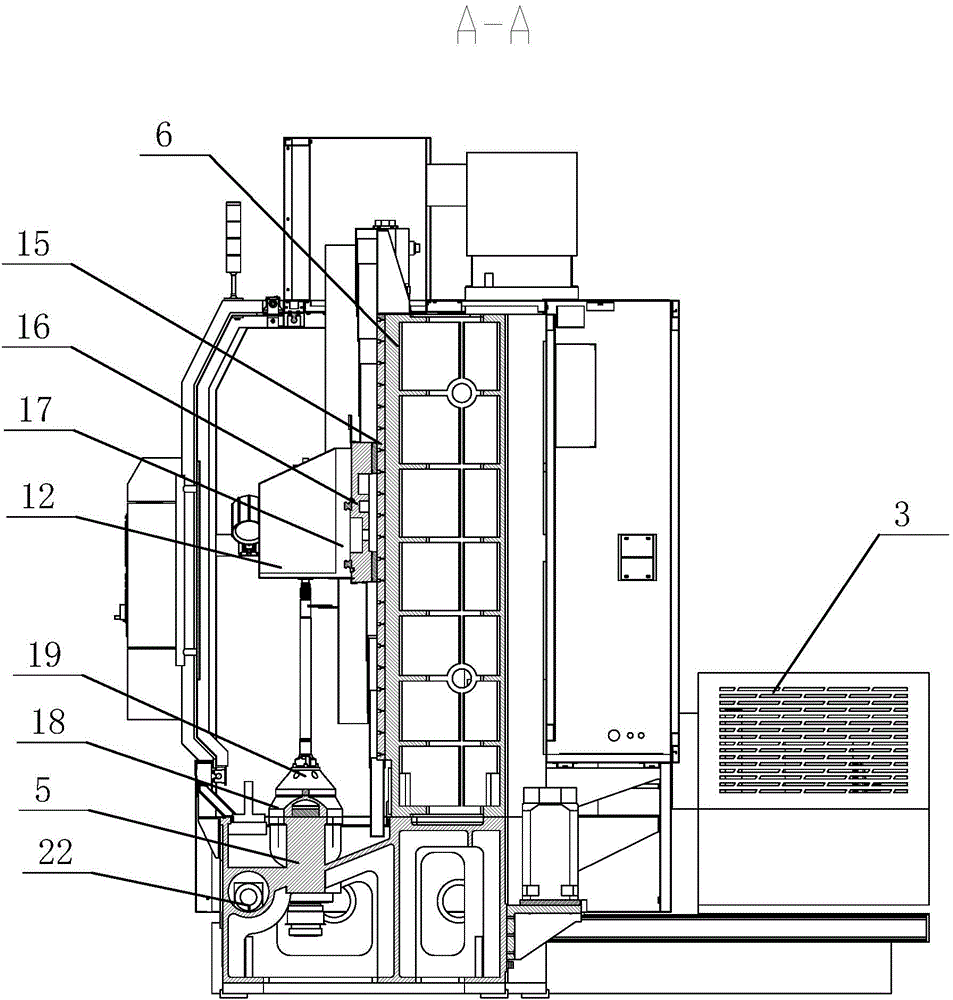
[0034] Such as Figure 1-6As shown, the present embodiment is a multi-spindle 18 numerical control vertical special lathe, multi-spindle 18 numerical control vertical special lathe, including bed base 1, main motor 2, hydraulic station 3 and numerical control system 4, bed base 1 is provided with vertical The processing mechanism includes two set...


PUM


Abstract

The invention relates to a multi-spindle numerical control vertical type special lathe, which comprises a base, wherein a processing mechanism is arranged on the base and comprises two vertical spindle units, the two spindle units are closely arranged along the transverse direction, a vertical column is arranged at the back side of each spindle unit, a vertical tail seat unit and two feeding units are arranged on each vertical column, and the two feeding units are respectively arranged at the two transverse sides of the corresponding tail seat unit; each tail seat unit comprises a first slide device, a tail seat is arranged on each first slide device, and two vertical tail seat sleeve cylinders are arranged at the lower part of each tail seat, are positioned above spindles, and are correspondingly arranged; each feeding unit comprises a second slide device and a transverse movement device, each transverse movement device is arranged on the corresponding second slide device, a knife holder is arranged on each transverse movement device, each first slide device and each second slide device can be moved on the corresponding vertical column along the vertical direction, and each transverse movement device is moved on the corresponding second slide device along the transverse direction. The multi-spindle numerical control vertical type special lathe has the advantages that multiple different types of camshaft parts can be simultaneously processed, and the production efficiency is high; the whole land occupation area of the equipment is small.

Description

technical field [0001] The invention relates to a vertical numerical control lathe, which belongs to the technical field of mechanical processing, in particular to a multi-spindle numerical control vertical special lathe. Background technique [0002] Camshaft parts belong to a relatively complex crankshaft, and are also key components of automobiles, motorcycles, internal combustion engines, and diesel engines. The main body of the camshaft is a cylindrical rod with approximately the same length as the cylinder, and there are several cams on it. Its function is to open or close the valve of the engine cylinder at an appropriate time. The camshaft doesn't look like a very special thing, but it can be called the heart of the engine. With the rapid development of the automobile industry and the internal combustion engine industry, the demand is increasing, and the requirements for machining accuracy are getting higher and higher. [0003] At present, camshaft parts are proce...

Claims


Application Information

Patent Timeline
Patent Type & Authority Applications(China)
IPC IPC(8): B23B9/08B23B23/00B23B19/02B23Q5/40B23Q11/00
CPCB23B9/08B23B23/00B23B2215/16B23Q1/70B23Q5/40B23Q11/0042B23Q11/0057
Inventor 毕卫民李辉张小尧刘鹏飞
Owner JINAN FIRST MACHINE TOOL GROUP
Why Eureka
Try Eureka