
Method for calibrating spectral wavelength of optical grating rotary light splitting spectrograph

A technology of spectral wavelength and calibration method, applied in the field of spectral wavelength calibration of grating rotating spectrometer, can solve the problems of reducing the accuracy of calibration curve, high cost, complicated curve fitting calculation, etc., achieving simple and effective calibration steps and reducing calibration work Reasonable and feasible effect of quantity and calibration

Inactive Publication Date: 2015-08-26
CHINA ELECTRONIS TECH INSTR CO LTD
View PDF8 Cites 11 Cited by
  • Summary
  • Abstract
  • Description
  • Claims
  • Application Information

AI Technical Summary

Problems solved by technology

[0007] (1) The workload of this method is relatively large. The calibration process in the early stage needs to control the rotation of the brushless DC motor more accurately for each light source, and feedback the position count of the optical encoder in time, and the curve fitting calculation in the later stage is also more complicated; (2) This method is inefficient, time-consuming, and costly. In order to meet the requirements of wavelength accuracy, it is necessary to use a variety of standard fiber laser light sources with different wavelength values, and the wavelength of the light source is required to be more evenly distributed within the range of 600nm to 1700nm. , so the calibration cost is high, and it is also difficult to find so many standard light sources that meet the above wavelength requirements; (3) The calibration accuracy of this method is low. First, if there are not enough standard light sources that meet the requirements, the accuracy of the calibration curve will be reduced. In addition, this method does not consider the error caused by the different grating constants of each spectrometer, so the calibration accuracy is low

Method used


Image

  • Method for calibrating spectral wavelength of optical grating rotary light splitting spectrograph
  • Method for calibrating spectral wavelength of optical grating rotary light splitting spectrograph
  • Method for calibrating spectral wavelength of optical grating rotary light splitting spectrograph

Examples


Embodiment Construction

[0043] The present invention will be further described in detail below in conjunction with the drawings and specific implementations:

[0044] A method for calibrating the spectral wavelength of a grating rotating spectrophotometer includes the following steps:

[0045] a Establish theoretical model of spectral wavelength calibration

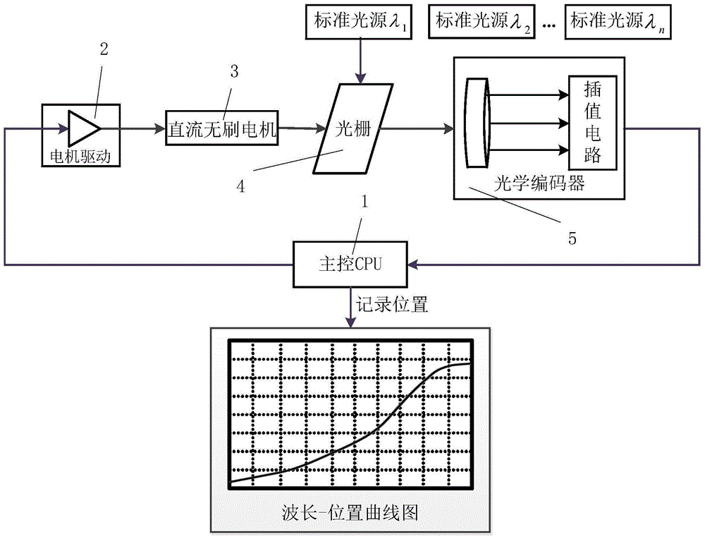
[0046] The wavelength tuning of the grating beam splitting system of the spectrometer is controlled by the angular position of the diffraction grating. The rotating shaft of the DC brushless motor and the rotating shaft of the optical encoder in the grating positioning system are directly fixed on the rotating shaft of the grating.

[0047] The purpose of this design is to facilitate direct drive and direct reading of the angular position of the grating.

[0048] The spectrometer to be calibrated adopts a sine wave output incremental laser rotary encoder. There are 81,000 engraved lines on the turntable, including two sine and cosine output count channel ...


PUM


Abstract

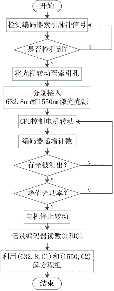
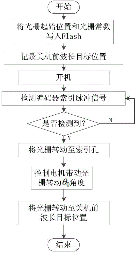
The invention discloses a method for calibrating the spectral wavelength of an optical grating rotary light splitting spectrograph. The method is characterized in that a relation between the optical wavelength and reading of an optical encoder is derived by using an optical grating equation working under a Littrow condition, and a theoretical calibration model is established; spectral wavelength calibration is carried out by using a two-point equation solving method; and finally, initial wavelength positioning is carried out by using calibration parameters in order to ensure the consistency in target position when different spectrographs measure gratings with the same wavelength. The method disclosed by the invention has the advantages that (1) the calibration steps are simple and effective, and the calibration workload and the calculation amount are reduced under the premise of ensuring the calibration precision; (2) the calibration work can be completed by only using two standard light sources with different wavelengths under the premise of ensuring the accuracy of the wavelength, the calibration time is short, the calibration efficiency is high, and the calibration cost is low; and (3) the calibration model is established through known theories, curve fitting is not required to be adopted, factors, which influence calibration, among different spectrographs are considered comprehensively, calibration is carried out more reasonably and more feasibly, and the calibration precision is higher.

Description

Technical field [0001] The invention relates to a method for calibrating the spectrum wavelength of a grating rotating spectrometer. Background technique [0002] At present, due to the advantages of large transmission capacity, high transmission rate, anti-electromagnetic interference, and strong confidentiality, optical fiber communication technology has been rapidly developed and widely used in various fields such as military, industry, agriculture, medical treatment and scientific research. The continuous improvement of the transmission rate and transmission accuracy of the optical fiber communication system is particularly important for the test of the optical fiber communication system. The relevant test instruments play an important role of "seemingly supporting roles, but actually critical". Whether it is an optical fiber communication system development unit or an optical fiber communication device development and production unit, a spectrum analyzer in the communication...

Claims


Application Information

Patent Timeline
Patent Type & Authority Applications(China)
IPC IPC(8): G01J3/28G01J3/18
Inventor 侯喜报张志辉刘磊韩顺利
Owner CHINA ELECTRONIS TECH INSTR CO LTD
Learn More