

Micro-nano bubble generation device and sewage purification system
A micro-nano bubble generation device technology, applied in flotation water/sewage treatment, flocculation/sedimentation water/sewage treatment, grease/oily substance/floating matter removal device, etc., can solve the problem of harsh micro-bubble conditions and need to be reused , limitations of scope of application and other issues, to achieve the effect of improving gas utilization, strong practicability, and strong innovation
- Summary
- Abstract
- Description
- Claims
- Application Information
AI Technical Summary
Problems solved by technology
Method used
Image

Examples
Embodiment Construction
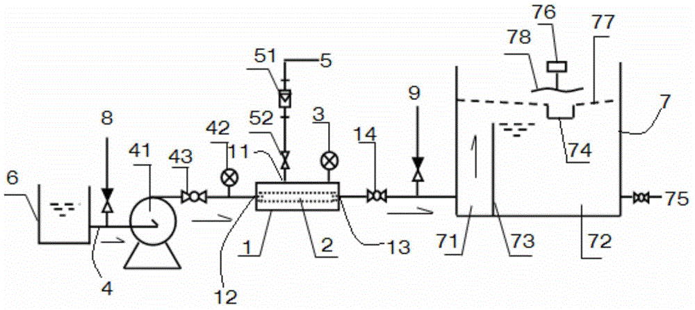
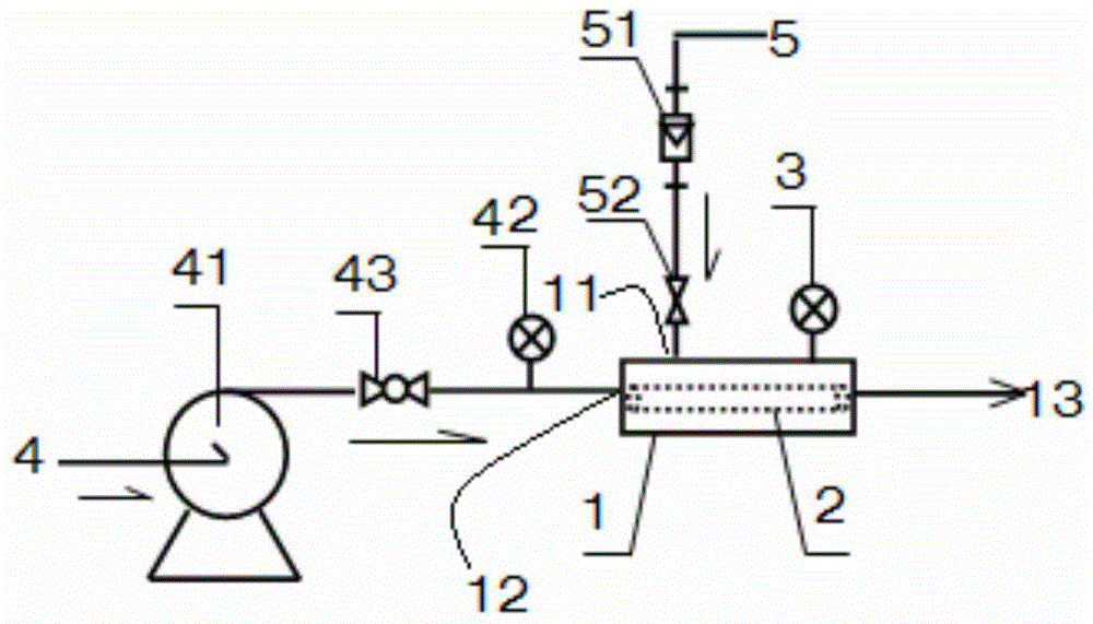
[0059] Specific embodiments of the present invention will be described in detail below in conjunction with the accompanying drawings. It should be understood that the specific embodiments described here are only used to illustrate and explain the present invention, and are not intended to limit the present invention.
[0060] In the present invention, unless stated to the contrary, the used orientation words such as "inside and outside" usually refer to the inside and outside of the contour of the corresponding object. Among them, it is known that the working principle of the membrane tube is that the corresponding substance permeates from the inside of the tube membrane to the outside, or from the outside to the inside, so the first side mentioned in the present invention is one of the inside and outside of the tube membrane. Alternatively, the second side is the other of the medial and lateral sides.
[0061] First of all, it needs to be explained that, in order to facilita...
PUM
 Abstract
Description
Claims
Application Information