
Vapor deposition equipment

A vapor deposition and equipment technology, applied in the field of display preparation, can solve the problems affecting the service life of the metal mask, the deformation of the stainless steel frame, the shadow effect, etc., so as to save the production cost and transportation cost, improve the convenience of use, and reduce the shadow effect. Effect

Active Publication Date: 2015-09-09
BOE TECH GRP CO LTD
View PDF1 Cites 7 Cited by
  • Summary
  • Abstract
  • Description
  • Claims
  • Application Information

AI Technical Summary

Problems solved by technology

[0002] Existing vapor deposition equipment needs to use a metal mask between the back plate and the plasma generation source to avoid film formation in the adhesive area of ​​the back plate. The main method is to weld the metal mask to the stainless steel frame and then placed in the vapor deposition equipment for use, but the metal mask using the iron-nickel alloy will react with the fluorine ions in the vacuum chamber, which will affect the service life of the metal mask. The existing practice is to use the metal mask After being welded on the stainless steel frame, it is plated with a layer of anti-plasma cloth layer, and then placed in the vapor deposition equipment for use, but the stainless steel frame is prone to deformation, and it is easy to produce shadow effects on the back plate, and metals of different sizes The mask needs to be used with metal frames of different sizes, which increases the cumbersomeness of the use of vapor deposition equipment

Method used


Image

  • Vapor deposition equipment
  • Vapor deposition equipment
  • Vapor deposition equipment

Examples


Embodiment Construction

[0048] The following will clearly and completely describe the technical solutions in the embodiments of the present invention with reference to the accompanying drawings in the embodiments of the present invention. Obviously, the described embodiments are only some, not all, embodiments of the present invention. Based on the embodiments of the present invention, all other embodiments obtained by persons of ordinary skill in the art without making creative efforts belong to the scope of patent protection of the present invention.

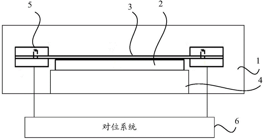
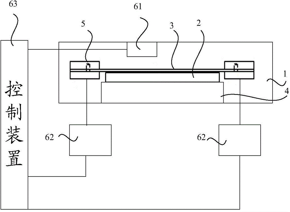
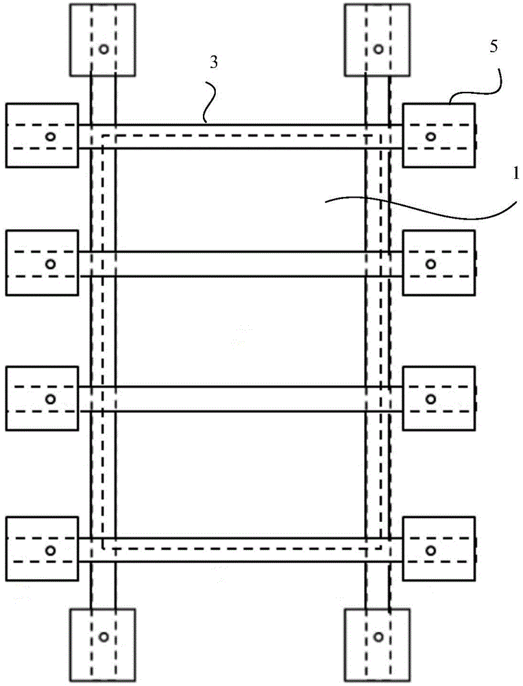
[0049] Such as figure 1 as shown, figure 1The partial structural schematic diagram of the first vapor deposition equipment provided in the embodiment of the present invention; the vapor deposition equipment provided by the present invention includes: a vacuum chamber 1, a back plate 2 located in the vacuum chamber 1, and a The metal mask 3 and the base 4 for supporting the backplane 2, the metal mask 3 is provided with an anti-plasma coating layer, ...


PUM


Abstract

The invention relates to the technical field of display manufacturing and discloses vapor deposition equipment. The vapor deposition equipment comprises a vacuum chamber, a back plate in the vacuum chamber, metal masks above the back plate, a substrate used for supporting the back plate, clamping mechanisms positioned on two opposite sides of the substrate and an alignment system, wherein an anti-plasma coating layer is arranged on each metal mask, each clamping mechanism is used for clamping the one end of the corresponding metal mask so as to draw the metal mask, the distance between every two clamping mechanism used for clamping the same metal mask is adjustable, the alignment system is used for controlling the clamping mechanisms to draw the metal masks with preset pull force and controlling the clamping mechanisms to adhere the metal masks at preset positions on the back plate. The vapor deposition equipment is more convenient to use and capable of reducing phenomena of shadow effects on the back plate.

Description

technical field [0001] The invention relates to the technical field of display preparation, in particular to a vapor deposition device. Background technique [0002] Existing vapor deposition equipment needs to use a metal mask between the back plate and the plasma generation source to avoid film formation in the adhesive area of ​​the back plate. The main method is to weld the metal mask to the stainless steel frame and then placed in the vapor deposition equipment for use, but the metal mask using the iron-nickel alloy will react with the fluorine ions in the vacuum chamber, which will affect the service life of the metal mask. The existing method is to use the metal mask After being welded on the stainless steel frame, it is plated with a layer of anti-plasma cloth layer, and then placed in the vapor deposition equipment for use, but the stainless steel frame is prone to deformation, and it is easy to produce shadow effects on the back plate, and metals of different sizes...

Claims


Application Information

Patent Timeline
IPC IPC(8): C23C16/458C23C16/04
CPCC23C16/4585H01L21/68728C23C14/042C23C16/042
Inventor 苏志玮
Owner BOE TECH GRP CO LTD
Learn More