Resistance furnace for brazing zinc electrolysis anode electric conducting cross beam and brazing method

A conductive beam, zinc electrolysis technology, applied in welding/welding/cutting items, electric heating devices, welding equipment, etc., can solve the problems of occupational health and working environment hazards of operators, increased tank voltage, affecting current efficiency, etc. The effect of improving occupational health and working environment, reducing unit consumption of DC power, and reducing ineffective power consumption

Active Publication Date: 2015-09-23
NORTHWEST RES INST OF MINING & METALLURGY INST
View PDF8 Cites 0 Cited by
  • Summary
  • Abstract
  • Description
  • Claims
  • Application Information

AI Technical Summary

Problems solved by technology

This technology has the following defects: 1) due to the inability to form a metallurgical bond between copper and lead
3) Due to the existence of a large area of ​​gaps on the copper / lead joint surface, an oxide layer is easily formed under the action of an acidic gas phase medium, which further increases the contact resistance, increases the cell voltage, and affects the current efficiency
4) During the casting process, due to the overheating of molten metal, a large amount of lead vapor is produced, which is harmful to the occupational health of operators and the working environment

Method used


Image

  • Resistance furnace for brazing zinc electrolysis anode electric conducting cross beam and brazing method
  • Resistance furnace for brazing zinc electrolysis anode electric conducting cross beam and brazing method

Examples


Embodiment Construction

[0021] The present invention will be further described below in conjunction with the drawings and specific embodiments.

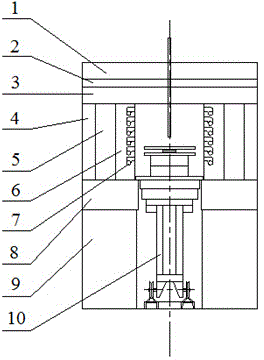
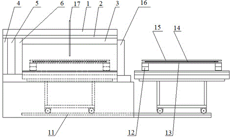
[0022] Such as figure 1 with figure 2 As shown, the resistance furnace of the present invention includes a U-shaped base 9 arranged horizontally, a U-shaped furnace bottom 8 is horizontally arranged on the base 9, a rail 11 is installed on the bottom surface of the base 9, and one end of the rail 11 is located in the base 9. The other end of the rail 11 extends out of the base 9; the rail 11 is provided with a traveling furnace car 10 that can reciprocate along the rail 11; a U-shaped shell is horizontally provided on the furnace bottom 8 and the open end of the shell faces the rail 11 extends from one end of the base 9 and is installed with a front furnace door 16. In the shell, a first side wall 4, an insulation layer 5 and a second side wall 6 are sequentially arranged in the direction from the inner wall of the shell to the middle of the shell; The first ...


PUM

PropertyMeasurementUnit
lengthaaaaaaaaaa
widthaaaaaaaaaa
thicknessaaaaaaaaaa

Abstract

The invention discloses a resistance furnace for brazing a zinc electrolysis anode electric conducting cross beam and a brazing method. The resistance furnace comprises a U-shaped base horizontally arranged, wherein the base has a furnace bottom; a rail is arranged on the bottom surface of the base, and is provided with an advancing furnace car capable of performing a reciprocating motion; a furnace body is arranged on the furnace bottom; a cavity is formed in the furnace body; electric furnace wires are arranged on the side wall of the cavity; a front furnace gate is formed in the side wall of the furnace body; the advancing furnace car is pushed into the base in use; and the working surface of the advancing furnace car and the cavity of the furnace body are formed to an empty cavity. A copper plate and lead plates with two specifications are prepared; one lead plate, the copper plate and the other one lead plate are laminated on the working surface of the advancing furnace car in sequence; brazing filler metals are laid in gaps among the plates; a pressure plate is covered; the advancing furnace car enters the base; after the segmented temperature rise and insulation is performed, the plates are discharged from the furnace for air cooling; the lead plates are welded; and the copper plate is sealed in the lead plates. The brazing method applies a brazing technology to weld heterogeneous metals, and solves the surface-surface metallurgic bonding problem of copper / lead heterogeneous metals.

Description

technical field [0001] The invention belongs to the field of welding technology, and relates to a brazing method for compounding copper and lead heterogeneous metals, in particular to a resistance furnace for brazing a conductive beam of a zinc electrolytic anode; the invention also relates to a brazing method using the resistance furnace Method for welding conductive beams of zinc electrolytic anodes. Background technique [0002] At present, the manufacturing method of the zinc electrolytic anode conductive crossbeam is copper and lead bimetallic casting. This technology has the following defects: 1) Due to the inability to form a metallurgical bond between copper and lead. Therefore, first tin-plate the copper surface and then inject metal lead liquid into the mold embedded with copper bars to realize the joint of copper and lead. Due to the poor bonding force and easy cracking of the copper / aluminum metal interface formed by tin, the contact resistance increases. 2) W...

Claims


Application Information

Patent Timeline
Patent Type & Authority Applications(China)
IPC IPC(8): B23K3/053B23K3/08B23K1/008B23K1/20
CPCB23K1/008B23K1/206B23K3/053B23K3/08B23K2103/12
Inventor 宋宝兴马进宋衎蒲敬文
Owner NORTHWEST RES INST OF MINING & METALLURGY INST
Why Eureka
Try Eureka