Ultrafast laser cutting method for miniature oil filter screen of engine

An ultra-fast laser and cutting method technology, applied in the direction of laser welding equipment, welding/cutting auxiliary equipment, auxiliary devices, etc., can solve the problems of low production efficiency and poor quality stability of microholes, and achieve high production efficiency and high cutting efficiency , the effect of improving production efficiency

Active Publication Date: 2022-02-01
XIAN AEROSPACE PROPULSION INST
View PDF6 Cites 1 Cited by
  • Summary
  • Abstract
  • Description
  • Claims
  • Application Information

AI Technical Summary

Problems solved by technology

[0006] The purpose of the present invention is to provide an ultra-fast laser cutting method for engine miniature oil filters, which mainly solves the technical problems of low production efficiency and poor quality stability of micropores in traditional laser cutting

Method used


Image

  • Ultrafast laser cutting method for miniature oil filter screen of engine
  • Ultrafast laser cutting method for miniature oil filter screen of engine
  • Ultrafast laser cutting method for miniature oil filter screen of engine

Examples


Embodiment 1

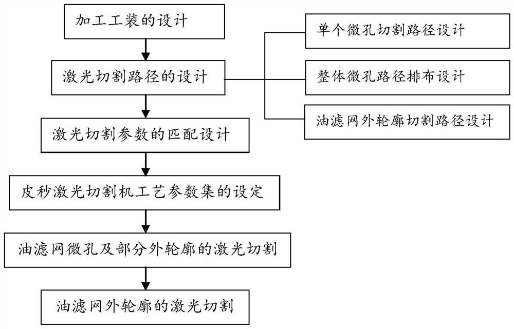
[0059] In this embodiment, the miniature oil strainer is a circular pure titanium product with a thickness of 0.1mm. Figure 1-Figure 6D , the specific cutting process is as follows:

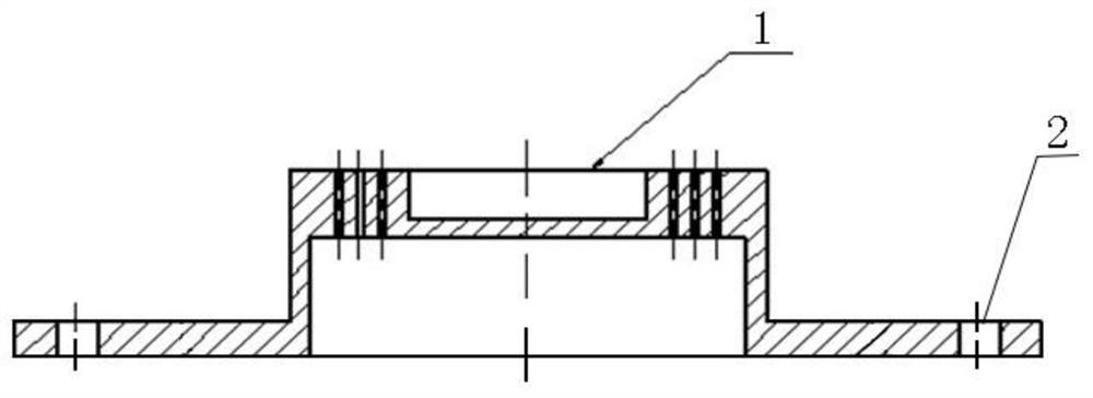
[0060] Step (1), design a processing tool according to the outer contour and size of the miniature oil filter screen (such as Figure 3A and Figure 3B shown), the processing tooling includes a raw material placement table 1 and a flange 2 fixedly connected to the raw material placement table 1, and the flange 2 connects the processing tooling to the working table of the picosecond laser cutting machine through bolts. Among them, the key to the processing tooling The original design is the raw material placement table 1. The raw material placement table 1 can ensure the parallelism between the raw material of the oil filter screen and the machine tool processing platform under the action of vacuum ejection. Design, wherein, evenly distributed circular holes are located on the raw material plac...

Embodiment 2

[0080] In the present embodiment, the miniature oil strainer is a square stainless steel product (such as figure 2 shown), the thickness is 0.3mm, the specific cutting process is as follows:

[0081] Step (1), design a processing tool according to the outer contour and size of the micro-oil filter, the design method of the processing tool is the same as step (1) in Example 1, wherein the diameter of the uniformly distributed circular holes ranges from Φ1. 0mm~Φ1.2mm, the round hole avoids a single groove, is located on the raw material placement platform 1, and is distributed in a symmetrical pattern around the groove; the shape of the single groove in this embodiment is square, and the depth range is 7mm to 10mm; The size of the single groove is larger than the size of the oil filter screen to be processed, and the lengths of the four sides are all increased by 0.5 mm to 1.5 mm on the basis of the length of one side of the oil filter screen to be processed.

[0082] Step (2...


PUM

PropertyMeasurementUnit
depthaaaaaaaaaa
thicknessaaaaaaaaaa
diameteraaaaaaaaaa

Abstract

The invention discloses an ultrafast laser cutting method for a miniature oil filter screen of an engine. The ultrafast laser cutting method mainly solves the technical problems that a traditional laser cutting method is low in production efficiency and poor in micropore quality stability. The cutting method comprises the following steps: designing a machining tool according to the outer contour and the size of the miniature oil filter screen; designing a laser cutting path and matching cutting parameters according to the size of micropores, the position distribution condition of the micropores and the size of the outer contour; then, cutting the micropores and a part of outer contour by using a picosecond laser cutting machine; and finally, recognizing the reserved uncut position of the outer contour of the oil filter screen by using a CCD image system of the millisecond laser cutting machine, and cutting off the outer contour. Thus, the ultrafast laser cutting machining of the miniature oil filter screen is achieved.

Description

technical field [0001] The invention relates to a metal strip or foil laser processing method, in particular to an ultrafast laser cutting method for an engine micro-oil filter. Background technique [0002] Micro oil filter is widely used in aerospace, automobile, petrochemical industry, installed in engine, valve, pipeline system, and has the functions of impurity filtration and flow control. The micropores of the micro oil filter are distributed at equal intervals on the titanium strip or stainless steel strip with a thickness of 0.1mm to 0.3mm. The range is about Φ0.15mm~Φ0.3mm, and the number ranges from tens to thousands. In order to ensure the performance of the micro-oil filter, there are strict requirements on the dimensional accuracy and position accuracy of the micro-holes, as well as the smoothness of the hole walls and edges. [0003] At present, the widely used processing method of micro oil filter is traditional pulse laser cutting. However, with the increas...

Claims


Application Information

Patent Timeline
Patent Type & Authority Applications(China)
IPC IPC(8): B23K26/382B23K26/70B23K37/04
CPCB23K26/382B23K26/702B23K37/0408Y02P70/10
Inventor 杨祎袁江王吉平解庆刘伟张玻溶刘钊
Owner XIAN AEROSPACE PROPULSION INST
Why Eureka
Try Eureka