A kind of electrolytic polishing equipment for inner wall of stainless steel pipe

A technology of electrolytic polishing and stainless steel tubes, applied in electrolytic components, electrolytic process, etc., can solve the problems of deteriorating air bubble outflow effect, failure to reach current density, hidden danger of large water pollution, etc., achieve good process stability and consistency, and economic benefits Good safety and prevent running, emitting, dripping and leaking

Active Publication Date: 2020-05-05
宣城品宙洁净科技有限公司
View PDF10 Cites 2 Cited by
  • Summary
  • Abstract
  • Description
  • Claims
  • Application Information

AI Technical Summary

Problems solved by technology

Such electrolytic polishing process has several serious defects: one, because the whole steel pipe inner surface is carrying out electrolytic polishing at the same time, and the electric current that the elongated cathode conductor structure can bear is very limited, and the result that causes is to be unable to reach the required current at all. The required current density, and the smaller the diameter of the steel pipe, the more serious the problem
[0006] 1. The polishing effect of this scheme is poor: when the movement direction of the cathode is opposite to the flow direction of the electropolishing solution, the outflow effect of the bubbles will be deteriorated, which will seriously affect the polishing quality
The horizontally arranged structure of steel pipes is also prone to the situation that the electrolytic polishing solution cannot fill the entire pipe, which in turn leads to partial failure of normal electrolysis.
In addition, the amount of electrolyte at the two ports of the steel pipe is difficult to control, and it is difficult to obtain the same current density and polishing time as the middle section of the steel pipe, and the polishing effect is difficult to meet the semiconductor industry standard
[0007] 2. The equipment occupies a large area: the standard length of the electropolishing tube required by the semiconductor industry is 6 meters. In the prior art, the steel tube is placed horizontally during electropolishing, and the cathode and the extension rod inserted into the steel tube are both rigid long conductors. This structural feature determines that the overall equipment length must exceed 12 meters
In the case of limited space, such a layout is difficult to produce a large number of steel pipes at the same time. In practical applications, only two steel pipes can be produced at the same time. The cost is high and the efficiency is very low, and the required length of the equipment is too long. Affect the efficiency of space utilization
[0008] 3. It is difficult to achieve the ideal flow rate of the electrolytic polishing solution in the tube: when using the existing technology for electrolytic polishing, each steel pipe is responsible for pumping the electrolytic polishing solution by a separate acid-resistant high-temperature centrifugal pump, but the electrolytic polishing solution is relatively viscous, and its specific gravity often reaches 1.7 above
However, the characteristics of the centrifugal pump determine that the flow rate is too small and it cannot work stably at all, and it is also easy to overheat and damage the pump head because the heat cannot be taken out in time
The minimum inner diameter of a single steel pipe is only about 4 mm. It is difficult to match a centrifugal pump with a suitable lift in actual use. Therefore, it can only work under the condition of a small flow rate, which makes the anode dissolved deposits easily on the cathode. Accumulate on the surface, thereby increasing the resistance and affecting the polishing process
When the attachment grows to a certain thickness, it may even directly contact the pipe wall, resulting in electric injury and scrapping of the product
[0009] Fourth, there are many residual pollutants, and wastewater treatment is difficult: because the steel pipes in production are placed horizontally, it is difficult to discharge a large amount of electrolytic polishing solution remaining inside the steel pipes after the electrolytic polishing is completed
A large amount of pollutants can only be brought into the wastewater treatment system after the subsequent cleaning process, which greatly increases the load of the wastewater treatment system and brings a greater hidden danger of water pollution
[0010] 5. It is difficult to maintain the specific gravity of the electrolytic polishing solution: because the electrolytic polishing solution contains concentrated sulfuric acid, it is very easy to absorb water from the air, resulting in a decrease in the specific gravity, and too high a water content will affect the quality of the electrolytic polishing
The current solution is to evaporate the water in the electropolishing solution by heating, but this solution consumes a lot of energy and takes a long time, which is not conducive to improving production efficiency
[0011] 6. There are potential safety hazards in the sealing joints at the steel pipe connections: Since the high-temperature electrolytic polishing solution must circulate inside the steel pipes and have a certain pressure, if the sealing joints connecting the steel pipes cannot work normally, it will bring great potential safety hazards
At the same time, it needs to be disassembled repeatedly during mass production, so it must be easy to disassemble and durable
[0012] 7. In the prior art, both ends of the steel pipe are closed to form a closed acid circuit. On the one hand, this method causes a large number of air bubbles generated during the electrolysis process to flow back into the electrolyte tank, which must be removed by the suction device, which greatly increases the cost of the waste gas treatment device. load and bring environmental hazards
Difficult to implement, high cost, high risk of leakage

Method used


Image

  • A kind of electrolytic polishing equipment for inner wall of stainless steel pipe
  • A kind of electrolytic polishing equipment for inner wall of stainless steel pipe
  • A kind of electrolytic polishing equipment for inner wall of stainless steel pipe

Examples


Embodiment 1

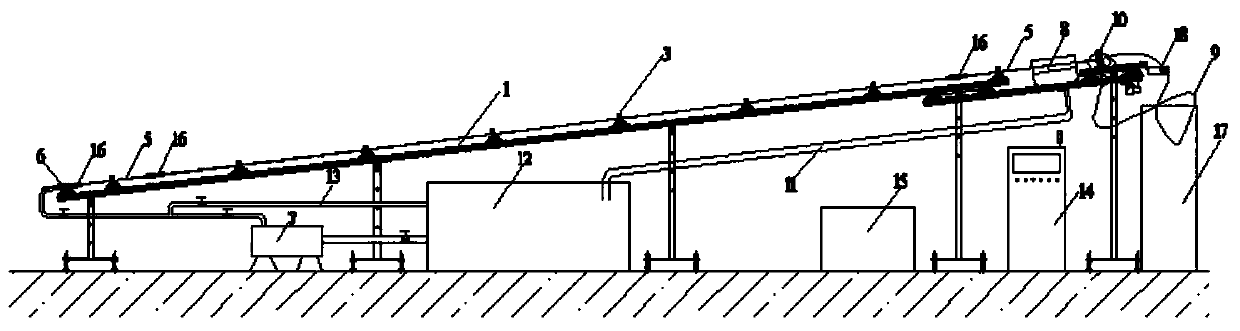
[0056] An electrolytic polishing equipment used for the inner wall of stainless steel pipes, the upper end of the equipment is equipped with a copper anode assembly frame 1, the inclination angle of the copper anode assembly frame 1 is 5-15°, and 10 to 20 anodes can be placed at one time product, the bottom of the copper anode assembly frame 1 is equidistantly provided with several brackets to fix the equipment, and the copper anode assembly frame 1 is provided with several V-shaped grooves 2, which are suitable for steel pipe products with various outer diameters , a pressing device 3 is arranged on the upper part of the V-shaped groove 2, a steel pipe 4 is arranged between the copper anode assembly frame 1 and the pressing device 3, and two ends of the steel pipe 4 are connected with extending Steel pipe 5, the diameter of the extension steel pipe 5 is the same as that of the steel pipe 4, the extension steel pipe 5 is 50-100cm long, and the left end of the extension steel pi...

Embodiment 2

[0070] 1. Example of production of 316L stainless steel pipe with an outer diameter of 12.7 mm (1 / 2 inch):

[0071] 1.1. Place 10 316L raw material steel pipes with an outer diameter of 12.7 millimeters and a length of 6 meters on the copper anode assembly frame at one time (the raw material pipes are processed by bright annealing);

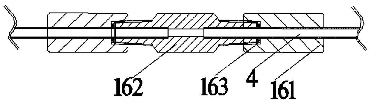
[0072] 1.2. The upper and lower ports of all steel pipes are connected with 304 extended steel pipes with a length of 800 mm and an outer diameter of 12.7 mm using the quick-twist joint assembly. There are 10 extension steel pipes at the top and bottom respectively, and the 10 extension steel pipes at the lower end are connected to the electrolyte distributor through the quick-twist joint assembly. The steel pipe extended at the upper end extends into the collector, and the upper port is opened.

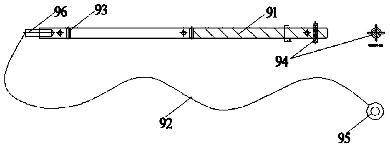
[0073] 1.3. Select the round copper rod with a diameter of 5 mm and a length of 800 mm as the cathode body. A PTFE externally threaded rod with a dia...

Embodiment 3

[0077] Embodiment 3: Effect embodiment of product or method

[0078] In the above-mentioned Example 2, ten 316L stainless steel pipes with a length of 6 meters were electrolyzed within 30 minutes, and a series of inspections were carried out after the conventional cleaning process was completed.

[0079] 1. The inner surface roughness of three positions at both ends and the center of each steel pipe is tested. Each position is tested at two points by Mitutoyo SJ-210 roughness meter. The actual measured inner surface roughness data is as follows: Figure 8 shown.

[0080] 2. All the steel pipes are cut open for visual inspection. The inner walls of the steel pipes are bright and electrolytically polished without any visible defects.

[0081] 3. Based on the international standard test method SEMATECH Test Method 91060573B in the semiconductor industry, the AES oxide layer thickness analysis of the steel pipe sample is carried out, and the results are as follows Figure 9 show...


PUM

PropertyMeasurementUnit
lengthaaaaaaaaaa
lengthaaaaaaaaaa
diameteraaaaaaaaaa

Abstract

The invention provides an electropolishing device for inner wall of stainless steel pipe, the upper end of the device is provided with a copper anode unit frame, the copper anode unit frame has an inclination angle of 5 to 15 degrees, and extension steel pipes are connected to both ends of a steel pipe, the left end of the extension steel pipe at the left end is provided with an electrolyte distributor, the electrolyte distributor is connected with a high-lift centrifugal pump through a pipeline, the right end opening of the extension steel pipe at the right end is connected with a collector,a flexible cathode is arranged in the steel pipe, a return pipe connected with an electrolyte tank is arranged at the bottom of the collector, a pressure relief pipeline is arranged between the upperend of the electrolyte tank and the outlet of the high-lift centrifugal pump, and a fully automatic control host and a high frequency pulse rectifier are arranged at the bottom of the right side of the copper anode unit frame. The device has compact structure, small floor space, high processing efficiency, good processing quality, convenient assembly and disassembly of components, long service life of the device and good economic benefits.

Description

technical field [0001] The invention relates to the technical field of integrated circuit chip manufacturing, in particular to an electrolytic polishing device for the inner wall of an ultra-high cleanliness stainless steel pipe used for transporting ultra-high-purity gas in the integrated circuit chip manufacturing industry. Background technique [0002] In the modern integrated circuit industry, the characteristic line width of the chip has reached the nanometer level. Therefore, ultra-high purity 316L stainless steel pipes must be used for the delivery of high-purity gases in the integrated circuit industry. The inner wall of this type of steel pipe must undergo high-quality electrolytic polishing, and the inner surface roughness must reach Ra 0.25 microns or even lower, otherwise, a very small amount of particles or impure substances will adhere to the rough inner wall, and the existence of such impurities It can cause the yield rate of the chip to drop significantly. ...

Claims


Application Information

Patent Timeline
Patent Type & Authority Patents(China)
IPC IPC(8): C25F7/00C25F3/24
CPCC25F3/24C25F7/00
Inventor 吴磊刚陶然
Owner 宣城品宙洁净科技有限公司
Why Eureka
Try Eureka