
CuIN2P-type red light emitting material with cuprous complexes

A technology of luminescent materials and complexes, applied in luminescent materials, copper organic compounds, electrical components, etc., can solve the problem that the luminous intensity cannot meet the application requirements, and achieve the effects of good phosphorescence emission performance, good solubility, and easy purification.

Inactive Publication Date: 2015-09-23
CHINA JILIANG UNIV
View PDF2 Cites 9 Cited by
  • Summary
  • Abstract
  • Description
  • Claims
  • Application Information

AI Technical Summary

Problems solved by technology

It's just that the luminous intensity of Cu(I) complex phosphorescent materials in the OLED working temperature range is still not up to the application requirements.

Method used


Image

  • CuIN2P-type red light emitting material with cuprous complexes
  • CuIN2P-type red light emitting material with cuprous complexes
  • CuIN2P-type red light emitting material with cuprous complexes

Examples


Embodiment 1

[0034] Preparation of a large number of microcrystalline samples: Weigh 0.5 mmol of CuI and dissolve it in 10 mL of acetonitrile, weigh 0.5 mmol of tris(2,5-xylyl)phosphine ligand and dissolve it in 8 mL of dichloromethane, and mix the two Mix the solutions, and stir to make the coordination reaction fully occur to obtain a colorless solution A; then weigh 0.5mmol of 2-PBO ligand and dissolve it in 8mL of acetonitrile, then add this solution to the above solution A, and stir to make it fully A coordination reaction occurs, and finally the obtained yellow reaction solution is rotary evaporated to remove all solvents, and dried in vacuum to obtain a yellow crystal powder as the product, with a yield of 97% (calculated as Cu).

Embodiment 2

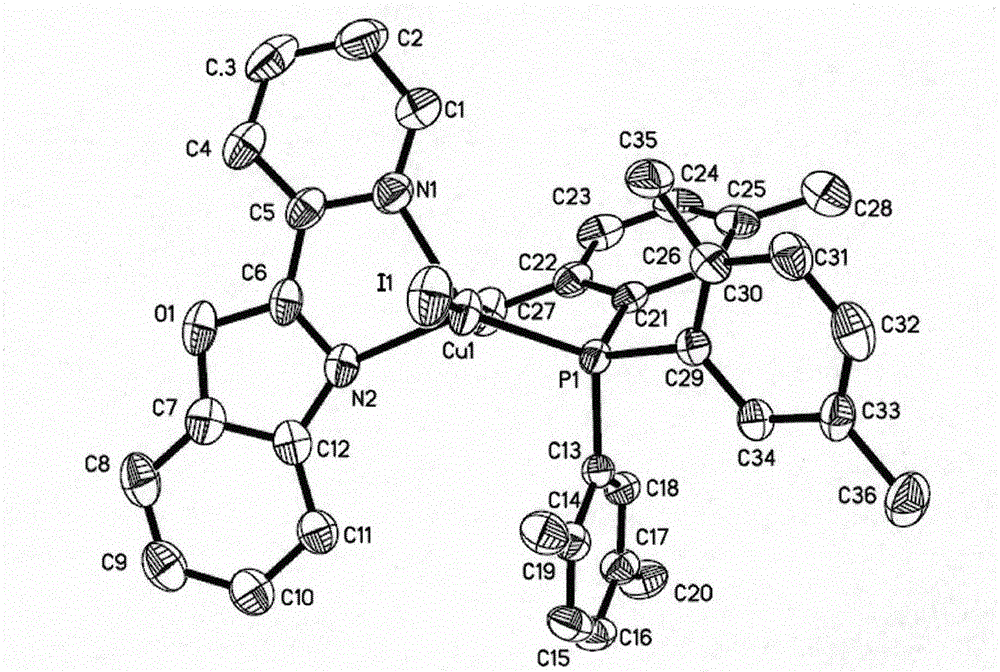
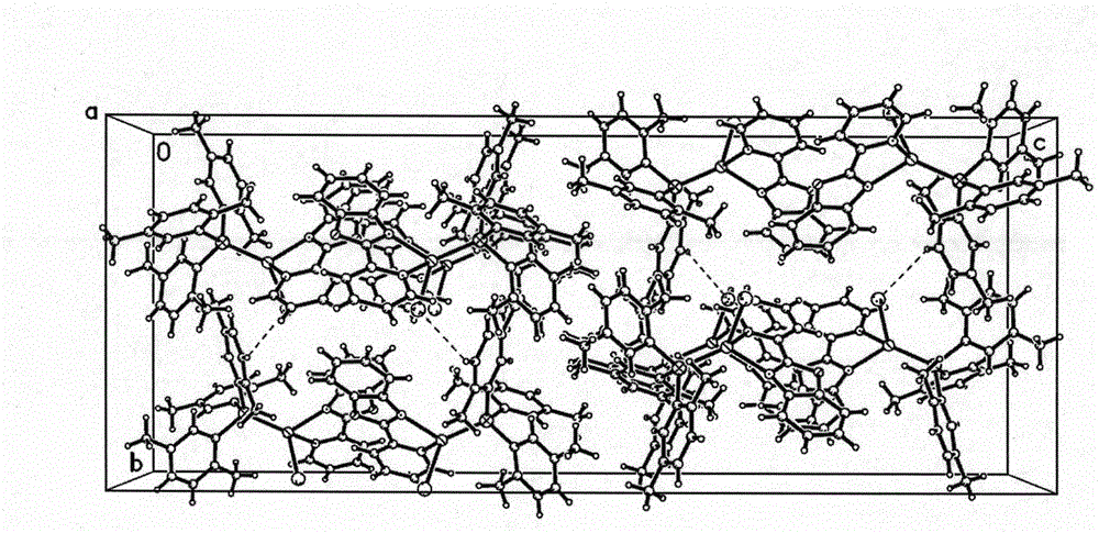
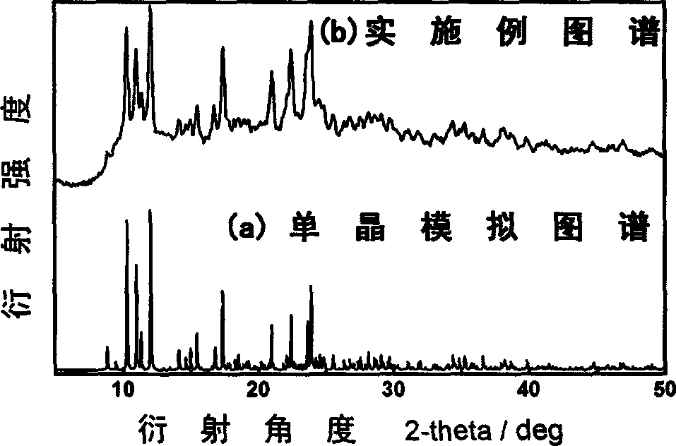
[0036] Synthesis of single crystal of phosphorescent cuprous complex CuI(2-PBO)(TXP-2,5): Weigh 0.1 mmol of CuI and dissolve it in 3 mL of acetonitrile, weigh 0.1 of tris(2,5-xylyl)phosphine Dissolve the ligand in 3mL of dichloromethane, mix the two solutions, and stir to make it fully undergo a coordination reaction to obtain a colorless solution A; then weigh 0.1mmol of 2-PBO ligand and dissolve it in 2mL of acetonitrile, Then add this solution into the above-mentioned solution A, and stir to make the coordination reaction fully occur, and finally filter the obtained yellow solution, cover the filtrate with n-hexane to promote the crystallization of the product, and after standing for several days, a large number of yellow blocky crystals are precipitated. A yellow bulk transparent crystal with a size of 0.38mm×0.30mm×0.23mm was selected for the X-ray single crystal diffraction structure test. The molecular structure of the compound is shown in the attached figure 1 , and i...


PUM


Abstract

The invention discloses a red phosphorescence CuIN2P-type light emitting material with cuprous complexes and a method for manufacturing the red phosphorescence CuIN2P-type light emitting material. Cuprous iodide and ligands carry out coordination reaction to obtain the phosphorescence complexes of the red phosphorescence CuIN2P-type light emitting material. A molecular structural formula of the red phosphorescence CuIN2P-type light emitting material is CuI(2-PBO)(TXP-2, 5), and the 2-PBO and the TXP-2, 5 in the formula respectively represent electrically neutral ligand 2-(2-benzoxazole) pyridine and (2, 5-xylyl) triphosphine. The red phosphorescence CuIN2P-type light emitting material and the method have the advantages that small molecules of the complexes are easy to purify, and the complexes are high in light emitting efficiency and can be easily dissolved by organic solvents; liquor of the cuprous iodine and liquor of the ligands directly carry out mixed reaction to obtain the red phosphorescence CuIN2P-type light emitting material, accordingly processes are simple and convenient, equipment is simple, raw materials are easily available, and the red phosphorescence CuIN2P-type light emitting material is low in cost; the ed phosphorescence CuIN2P-type light emitting material not only can be used as a photoluminescence red light material, but also can be used as a phosphorescence material for a light emitting layer in an electroluminescence device with multiple layers of organic materials, and the like.

Description

technical field [0001] The invention relates to the technical field of luminescent materials, to the fields of photoluminescent materials and electroluminescent materials, in particular to the field of organic electroluminescent materials. Background technique [0002] Luminescent materials include photoluminescence and electroluminescence in two categories of applications. Photoluminescence refers to the phenomenon in which an object is irradiated by an external light source, thereby obtaining energy to generate excitation and finally lead to luminescence. Photoluminescence can be caused by ultraviolet radiation, visible light and infrared radiation. Photoluminescent materials can be used in fluorescence analysis, traffic signs, tracking monitoring, agricultural light conversion film, scintillator in nuclear detection technology, fluorescent light collector in solar energy conversion technology, etc. Electroluminescence (EL for short) refers to the phenomenon that lumines...

Claims


Application Information

Patent Timeline
IPC IPC(8): C09K11/06C07F1/08H01L51/54
Inventor 柴文祥宋莉陶晓栋秦来顺沈杭燕梁佳萍田光磊陈智陈海潮魏钦华陈忠奉
Owner CHINA JILIANG UNIV
Learn More