
Broadband high-selectivity balanced band-pass filter based on multimode resonators

A multi-mode resonance and high selectivity technology, applied in resonators, waveguide devices, circuits, etc., can solve the problems of narrow bandwidth of balanced filters, poor differential mode out-of-band suppression, complex structure processing, etc., to facilitate processing and integration , high common-mode rejection, and simple structure

Inactive Publication Date: 2015-09-23
NANJING UNIV OF SCI & TECH
View PDF2 Cites 13 Cited by
  • Summary
  • Abstract
  • Description
  • Claims
  • Application Information

AI Technical Summary

Problems solved by technology

Although the design theory of this design method is relatively simple, because the structure needs to be loaded with lumped elements, the structure processing is complicated and the error increases
The bandwidth of the balanced filter designed from the outside is narrow, and the 3dB relative bandwidth is only 8.92%.
[0004] In 2012, Wenjie Feng and Wenquan Che published "Novel Wideband Differential Bandpass Filters Based on T-Sharped Structure" in IEEE Transaction.Microwave Theory Technique (vol.60, no.6, pp.1560-1568, 2012), proposing Based on the T-shaped structure to realize the balanced output of the signal and the band-pass characteristics of the dual-mode, although the structure of this design method is relatively simple, the common-mode rejection effect is only 14.5dB, and the differential-mode out-of-band rejection is poor
Although this design does not require a ground hole and the structure is relatively simple, the common-mode rejection is only limited to the corresponding differential-mode frequency band, the out-of-band rejection of both common-mode and differential-mode is poor, and the insertion loss is large

Method used


Image

  • Broadband high-selectivity balanced band-pass filter based on multimode resonators
  • Broadband high-selectivity balanced band-pass filter based on multimode resonators
  • Broadband high-selectivity balanced band-pass filter based on multimode resonators

Examples


Embodiment 1

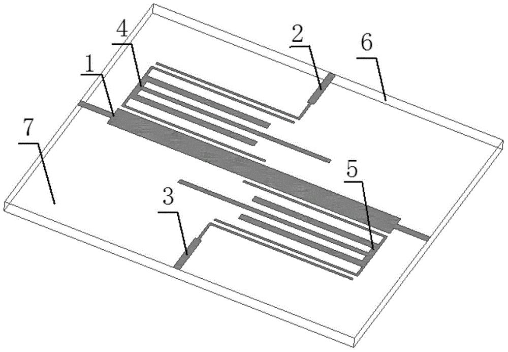
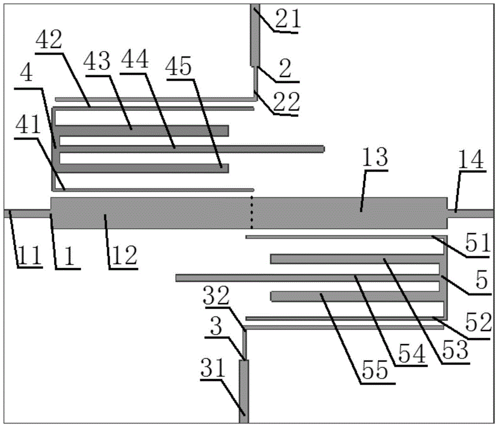
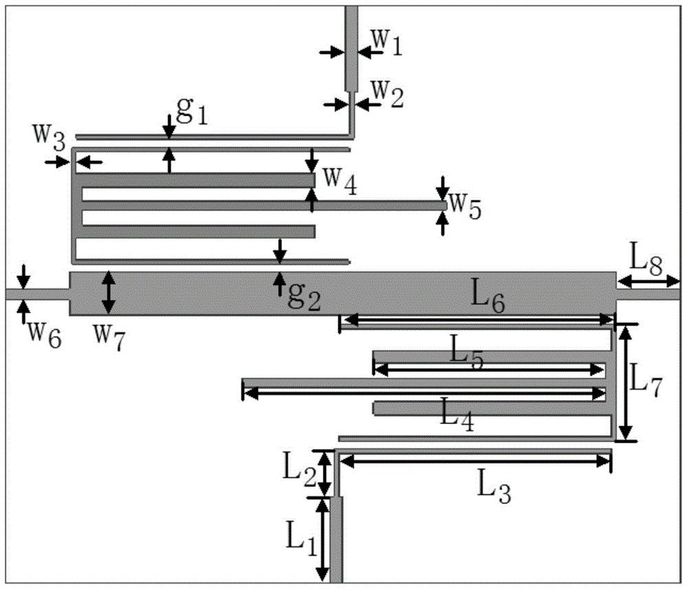
[0025] The structure of a broadband high-selectivity balanced bandpass filter based on multimode resonators is as follows figure 1 As shown, the top view is as figure 2 As shown, the relevant dimensions and specifications are as follows image 3 shown. The dielectric substrate 6 used has a relative permittivity of 3.55, a thickness of 0.508 mm, and a loss tangent of 0.0035. combine image 3 , the size parameters of the balanced filter are as follows: W 1 = 1.2mm, W 2 = 0.4mm, W 3 = 0.4mm, W 4 = 1.2mm, W 5 = 0.8mm, W 6 = 1.13mm, W 7 = 4mm, L 1 = 8mm, L 2 =4.4mm, L 3 =25.4mm,L 4 =33.8mm,L 5 =22.2mm, L 6 =10.8mm, L 7 =6mm, g 1 =0.15mm 2 = 0.1mm. The total area of ​​the balanced filter excluding the conduction band of the 50 ohm microstrip line is 34.9×50.8mm 2 , the corresponding guide wavelength size is 0.36λ g ×0.53λ g , where λ g is the guided wavelength corresponding to the center frequency of the passband.

[0026] The balanced filter of this example...


PUM


Abstract

The present invention discloses a broadband high-selectivity balanced band-pass filter based on multimode resonators. The band-pass filter comprises an input port feeder, a first output port feeder, a second output port feeder, a first multimode resonator and a second multimode resonator which are arranged on the upper surface of a dielectric substrate, and a metal earth plate arranged on the lower surface of the dielectric substrate, wherein both the first and second multimode resonators are symmetric stub-loaded multimode resonators; wherein the input port feeder comprises symmetrically connected first and second input port feeders; the first multimode resonator comprises two quarter-wave resonators, and three open-ended symmetric loading units; the second multimode resonator comprises two quarter-wave resonators, and three open-ended symmetric loading units. The broadband balanced band-pass filter according to the present invention has advantages such as broad stopband, minimized size, high common-mode rejection, high selectivity and low costs, and is quite suitable for modern wireless communication systems.

Description

technical field [0001] The invention relates to the technical field of microwave passive devices, in particular to a broadband high-selectivity balanced bandpass filter based on a multimode resonator. Background technique [0002] In recent years, with the development of Modular Building Block (MBB) and Monolithic Microwave Integrated Circuit (MMIC), low cost, high integration, and miniaturization have become the key elements in the integrated design of modern wireless communication systems. very important consideration. The balanced filter is an independent microwave passive device, which has higher environmental noise immunity, better dynamic range, and lower electric field interference than the single-port filter. The balanced filter realizes the passband range in the radio frequency circuit The function of internal differential mode signal transmission and common mode signal suppression plays an extremely important role in the construction of modern high-speed wireless ...

Claims


Application Information

Patent Timeline
IPC IPC(8): H01P1/203H01P7/08
Inventor 张钢蔡传涛王雪道王建朋
Owner NANJING UNIV OF SCI & TECH
Learn More