High temperature resistance type solidified shell thickness electromagnetic ultrasonic frequency sweep detection method and apparatus

A technology of electromagnetic ultrasonic and solidified shell, which is applied in measuring devices, using ultrasonic/sonic/infrasonic waves, instruments, etc., can solve the problems of human body and environmental impact, heavy measurement workload, and difficulty in predicting changes in the thickness of solidified shells, etc. Achieving the effect of high temperature and universality

Active Publication Date: 2015-10-07
CHONGQING UNIV
View PDF4 Cites 14 Cited by
  • Summary
  • Abstract
  • Description
  • Claims
  • Application Information

AI Technical Summary

Problems solved by technology

In the experimental measurement method, the nail shooting method is mainly used. The steel nail containing sulfur tracer is injected into the continuous casting slab in the secondary cooling zone, and the sulfur print analysis and low magnification are used to detect the concentration of the nail in the solid phase and liquid phase area of ​​the casting slab. The thickness of the solidified billet shell and the position of the liquid phase hole are determined by the topography of the solidified billet shell. This experimental method is mature in technology, high in precision, and the result is intuitive and reliable, but it belongs to off-line destructive testing, and the measurement workload is heavy; The cold zone pierces the solidified slab shell to allow the unsolidified liquid steel to flow out, and then conducts online detection of the thickness of the solidified slab shell. This detection method is destructive and the on-site operation is very difficult; The position of the bulge is used to determine the position of the liquid core. This measurement method is intuitive and the device is simple, but it can only roughly estimate the position of the end of the liquid core. The radiation method is mainly based on the use of a cobalt ray source, which is detected by a Geiger counter after the ray source passes through the continuous casting slab. The thickness of the solidified shell is detected by the change of ray intensity. The technical idea of ​​this method is feasible, but the radioactive pollution of the radioactive source will have a certain impact on the human body and the environment.
The numerical model method is based on the one-dimensional or two-dimensional unsteady heat transfer control equation, and uses the finite element difference calculation method to calculate the internal temperature field of the continuous casting slab, and then determine the internal shape of the continuous casting slab. This method is low in cost, but the model solution Accuracy depends on accurate boundary conditions, but unsteady continuous casting production determines that it is difficult to determine accurate boundary conditions. At the same time, the model calculation takes a long time to converge, and it is difficult to predict the change of solidified slab shell thickness online in real time
The strain test method determines the position of the solidification end of the continuous casting slab by installing foil resistance strain gauges on the relevant sectors of the continuous casting slab and monitoring the mutation point of the strain change on-line. This method has poor reliability and sensitivity, but is affected by the high temperature on site Due to the influence of radiation, water mist in the secondary cooling zone, complex forces on the fan section or work rolls, etc., the repeatability of the test results is poor, and it cannot be popularized and applied in industrial production sites
[0005] In summary, the online non-destructive testing of solidified slab shell thickness and liquid core end position in the continuous casting process is of great significance for improving the quality of continuous casting slabs in the continuous casting process and improving the automation level of continuous casting production. None of the shell thickness detection methods fundamentally solve the field application problems in industrial production

Method used


Image

  • High temperature resistance type solidified shell thickness electromagnetic ultrasonic frequency sweep detection method and apparatus
  • High temperature resistance type solidified shell thickness electromagnetic ultrasonic frequency sweep detection method and apparatus
  • High temperature resistance type solidified shell thickness electromagnetic ultrasonic frequency sweep detection method and apparatus

Examples


Embodiment Construction

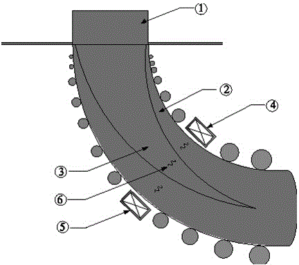
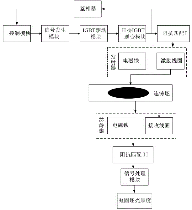
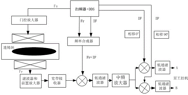
[0030] Due to the different characteristics of ultrasonic propagation speed and attenuation strength in the solid phase and liquid phase, the electromagnetic ultrasonic receiver detects the ultrasonic signal transmitted through the continuous casting slab, and its transit time will change with the thickness of the solidified slab shell, and the thickness of the solidified slab shell The relationship between d and ultrasonic transit time is:

[0031] d = ( τ - D V ‾ l ) 2 ( 1 V ‾ s - 1 ...


PUM


Abstract

The invention discloses a high temperature resistance type solidified shell thickness electromagnetic ultrasonic frequency sweep detection method and apparatus. Internal and external sides of a continuous casting blank are correspondingly provided with an electromagnetic ultrasonic generator and an electromagnetic ultrasonic receiver. Under the effect of high power burst radio-frequency signals, the exciting coil of the electromagnetic ultrasonic generator inducts eddy current on the surface of a continuous casting blank skin layer; the eddy current furthermore generates alternating Lorentz force and ultrasonic waves under the effect of a DC bias magnetic field, wherein the ultrasonic waves penetrate the continuous casting blank and are received by the electromagnetic ultrasonic receiver. A frequency sweep circuit is in cooperation with filters of different cut-off frequencies in order to detect amplitudes and phases of transmitted waves of different sweep frequencies; through phases of two different sweep frequencies, the transition time of the electromagnetic ultrasonic waves in the continuous casting blank can be obtained, and then the thickness of a solidified shell can be calculated. The method and apparatus can effectively avoid the influence of surface high temperature radiation and water mist environment in a continuous casting production site, and meet the requirements of measuring different surface temperatures and different casting steels of casting blanks.

Description

technical field [0001] The invention relates to an on-line non-destructive detection method and device for the thickness of the solidified slab shell in the continuous casting process of iron and steel, specifically refers to the long-term and accurate on-line detection of the thickness of the slab shell and the position of the solidified end during the solidification and forming process of the continuous casting slab during the continuous casting of iron and steel. Non-destructive testing. This measuring device is mainly used in the on-line non-destructive testing of the thickness of the solidified slab shell and the position of the solidification end in continuous casting of iron and steel. Improve the production quality of continuous casting slabs, and reduce and prevent steel breakout production accidents. Background technique [0002] During the continuous casting process of iron and steel, the thickness of the solidified slab shell and the position of the solidified e...

Claims


Application Information

Patent Timeline
Patent Type & Authority Applications(China)
IPC IPC(8): G01B17/02
CPCG01B17/02
Inventor 欧阳奇张兴兰沈志熙彭松张伟庆陈希梦仲元昌
Owner CHONGQING UNIV
Why Eureka
Try Eureka