Enhanced radio frequency inductively coupled plasma discharge device

A radio frequency inductive coupling, plasma technology, applied in the direction of plasma, electrical components, etc., can solve the problem that the plasma density is difficult to reach a high level, and achieve the effect of increasing the plasma density, increasing the area of ​​the hysteresis curve, and widening the working range

Active Publication Date: 2015-10-14
HARBIN INST OF TECH
View PDF4 Cites 17 Cited by
  • Summary
  • Abstract
  • Description
  • Claims
  • Application Information

AI Technical Summary

Problems solved by technology

[0006] The purpose of the present invention is to solve the problem that the plasma density is difficult to reach a high value due to the weak collision of the exist...

Method used


Image

  • Enhanced radio frequency inductively coupled plasma discharge device
  • Enhanced radio frequency inductively coupled plasma discharge device
  • Enhanced radio frequency inductively coupled plasma discharge device

Examples


specific Embodiment approach 1

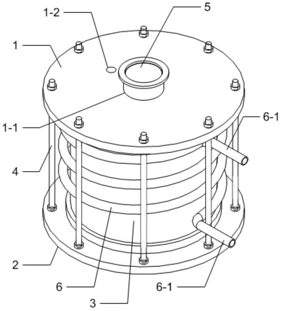
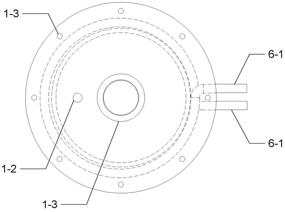
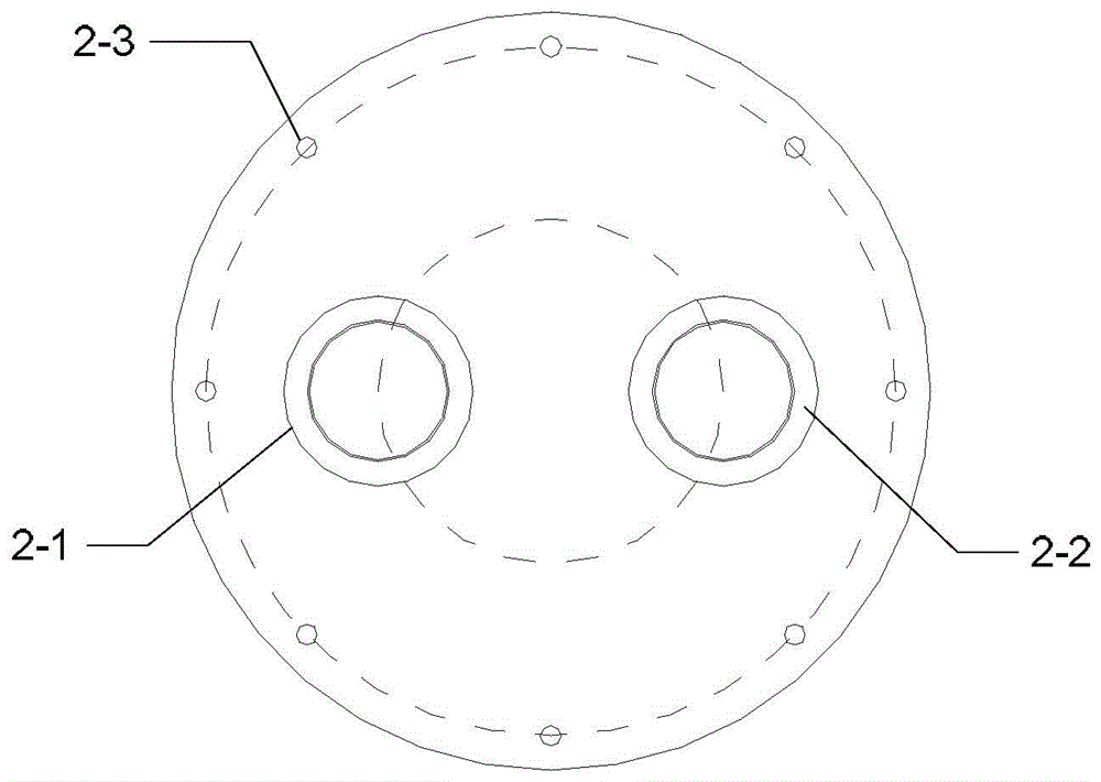
[0021] Specific implementation mode one: the following combination Figure 1 to Figure 5 Describe this embodiment mode, the enhanced radio frequency inductively coupled plasma discharge device described in this embodiment mode, it comprises upper end cover 1, lower end cover 2, cylindrical quartz glass tube 3, a plurality of long stem bolts 4, inner electrode coil 5 and outer Electrode coil 6;

[0022] The upper end cover 1, the lower end cover 2 and the cylindrical quartz glass tube 3 together form a vacuum chamber.

[0023] The outer part of the upper end cover 1 beyond the cylindrical quartz glass tube 3 is evenly distributed with a plurality of upper end installation holes 1-3 along the circumferential direction. The center position of the upper end cover 1 is provided with an inner coil installation hole 1-1. There is an air inlet 1-2, and the air inlet 1-2 communicates with the air chamber of the vacuum chamber;

[0024] The outer portion of the lower end cover 2 beyon...

specific Embodiment approach 2

[0031] Embodiment 2: In this embodiment, Embodiment 1 is further described. Both the inner electrode coil 5 and the outer electrode coil 6 are made of hollow copper tubes.

[0032] A connection terminal is provided at both ends of the hollow copper tube of the inner electrode coil, which is used for connecting cold water and electrically connecting with an external control system. The two hollow copper electrodes have water channels inside to cool the discharge.

specific Embodiment approach 3

[0033] Embodiment 3: In this embodiment, Embodiment 1 is further described. The outside of the hollow copper tube is covered with a heat-shrinkable tube for insulation between tubes.


PUM


Abstract

The invention relates to an enhanced radio frequency inductively coupled plasma discharge device and belongs to the low-temperature plasma application technical field. According to an existing ICP discharge device, the density of plasmas is difficult to achieve a high numerical value due to weak collision, while, with the enhanced radio frequency inductively coupled plasma discharge device of the invention adopted, the above situation can be avoided. The enhanced radio frequency inductively coupled plasma discharge device comprises an upper end cover, a lower end cover, a cylinder quartz glass tube, a plurality of long rod bolts, an inner electrode coil and an outer electrode coil; the upper end cover, the lower end cover and the cylinder quartz glass tube jointly form a vacuum cavity air chamber; a plurality of upper end mounting holes are uniformly distributed at the outer edge portion of the upper end cover along the circumferential direction of the upper end cover; an inner electrode coil mounting hole and an air inlet are formed in the upper end cover; a plurality of lower end mounting holes are uniformly distributed at the outer edge portion of the lower end cover along the circumferential direction of the lower end cover; a measurement hole and a vacuumizing hole are formed in the lower end cover, wherein the measurement hole is used for accommodating a probe-class measuring component, and the vacuumizing hole is connected with a vacuumizing system through a vacuum corrugated pipe; the outer circumferential surface of the cylinder quartz glass tube is provided with the outer electrode coil; and the inner electrode coil is arranged in the vacuum cavity air chamber and is installed in the inner electrode coil mounting hole.

Description

technical field [0001] The invention relates to a large-area and stable plasma discharge reaction device which can be used for low-pressure generation, and belongs to the application technical field of low-temperature plasma. Background technique [0002] Material surface modification and surface treatment processes have been widely used in the global manufacturing industry. Traditional processes mainly include: thermal spraying, laser surface modification, electroplating, electroless plating and chemical transfer film, all of which have made great progress. develop. However, for some materials with special structures and special properties, for example, in the processing of ultra-large-scale integrated circuit manufacturing processes, it is required to etch nano-scale groove widths on large-area wafers, and with the increasing technical requirements, more and more Thin etch line width is difficult to achieve with traditional techniques. Therefore, a new process technology...

Claims


Application Information

Patent Timeline
IPC IPC(8): H05H1/46
Inventor 聂秋月韩雪张仲麟王志斌孔繁荣
Owner HARBIN INST OF TECH
Why Eureka
Try Eureka