
Anti-corrosion structure for chimney and construction method thereof

A construction method and chimney technology, applied in building components, building insulation materials, building types, etc., can solve problems such as multiple welding quality problems, long construction period, chimney corrosion, etc., and achieve low construction environment requirements, short hardening time, and construction. short cycle effect

Active Publication Date: 2015-10-21
BEIJING CPCEP ENERGY CONSERVATION & ENVIRONMENTAL PROTECTION TECH CO LTD
View PDF5 Cites 3 Cited by
  • Summary
  • Abstract
  • Description
  • Claims
  • Application Information

AI Technical Summary

Problems solved by technology

The current desulfurization system generally adopts limestone-gypsum wet desulfurization technology. After the flue gas passes through the desulfurization system, it is transformed into moist flue gas and wet flue gas. Wet flue gas, wet flue gas and the condensate produced are highly corrosive. Serious threat to the operation of equipment after the desulfurization system
[0003] In addition, most flue gas desulfurization systems have canceled the GGH (flue gas heater), and most of the existing operating chimneys are designed according to the design criteria of dry flue gas chimneys, which are not suitable for the operating environment of wet flue gas, so many The chimney of the thermal power plant has a large area of ​​corrosion, which seriously affects the safe and stable operation of the entire power plant system
[0004] Based on the above problems, there are currently anti-corrosion treatments by welding titanium plates inside the chimney, but most of them have the following problems: 1) The construction period is long and the labor intensity of the workers is high; 2) Due to the poor welding environment on site, there are More welding quality problems; 3) The base of the chimney is prone to smoke leaks due to welding quality problems, resulting in corrosion

Method used


Image

  • Anti-corrosion structure for chimney and construction method thereof

Examples


Embodiment Construction

[0015] In order to better understand the purpose, structure and function of the present invention, a chimney anti-corrosion structure and its construction method of the present invention will be further described in detail below in conjunction with the accompanying drawings.

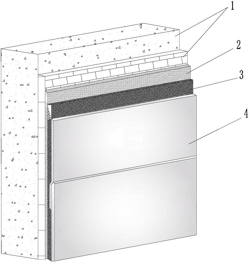
[0016] Such as figure 1 As shown, the anticorrosion structure of the chimney of the present invention comprises a primer layer 2, an adhesive layer 3 and a titanium plate layer 4 arranged in sequence, the primer layer 2 is coated on the chimney base 1, and the titanium plate layer 4 passes through the adhesive layer 3 is glued on the base coat 2. Wherein, the titanium plate layer 4 includes a plurality of titanium plates, and the multiple titanium plates are overlapped with each other and adhered to the primer layer 2 through the adhesive layer 3 to form the titanium plate layer 4 .

[0017] The chimney anticorrosion structure of the present invention can adapt to the operating environment of the wet fl...


PUM


Abstract

The invention discloses an anti-corrosion structure for a chimney. The anti-corrosion structure comprises a first coat (2), an adhesive layer (3) and a titanium plate layer (4) which are arranged in sequence, wherein a chimney base (1) is coated with the first coat (2), and the titanium plate layer (4) adheres to the first coat (2) through the adhesive layer (3). The invention further discloses a construction method of the anti-corrosion structure for the chimney. The method comprises the steps of cleaning the chimney base, coating the cleaned chimney base with the first coat material, applying adhesive and sticking a titanium plate after the first coat material on the chimney base is solidified, and conducting inspection and repair. According to the method, the lapped titanium plate is directly stuck onto the structural layer of a chimney by means of the titanium plate adhesive. The method has the advantages that construction period is short, the requirement for the site construction environment is low, and the problem that titanium plate welding quality is poor due to poor construction site welding environment is solved.

Description

technical field [0001] The invention relates to a chimney anticorrosion technology, in particular to a chimney anticorrosion structure and a construction method that can be used in industries such as electric power, cement, metallurgy, and chemical industry. Background technique [0002] In order to meet the requirements of the national environmental protection policy, the flue gas of domestic large-scale thermal power plants must be desulfurized before being discharged into the atmosphere. The current desulfurization system generally adopts limestone-gypsum wet desulfurization technology. After the flue gas passes through the desulfurization system, it is transformed into moist flue gas and wet flue gas. Wet flue gas, wet flue gas and the condensate produced are highly corrosive. It seriously threatens the operation of equipment after the desulfurization system. [0003] In addition, most flue gas desulfurization systems have canceled the GGH (flue gas heater), and most of...

Claims


Application Information

Patent Timeline
Patent Type & Authority Applications(China)
IPC IPC(8): E04H12/28E04B1/64
Inventor 单选户江浩唐晓犇白云峰张如意
Owner BEIJING CPCEP ENERGY CONSERVATION & ENVIRONMENTAL PROTECTION TECH CO LTD
Learn More