Working method of real scene navigation system
A technology of a navigation system and a working method, which is applied in the field of navigation, and can solve problems such as the delay of the navigator instruction navigation instruction image, the wrong driving route of the driver, and the low accuracy of the navigation signal, so as to achieve good guidance, improved work reliability, and real-time performance. Good results
- Summary
- Abstract
- Description
- Claims
- Application Information
AI Technical Summary
Problems solved by technology
Method used
Image
Examples
Embodiment 1
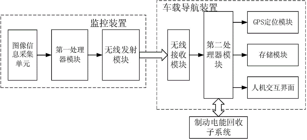
[0034] figure 1 A functional block diagram of the real scene navigation system of the present invention is shown.
[0035] like figure 1 As shown, the real-scene navigation system of the present invention includes: a navigation device and a camera; the navigation device includes: a gyroscope for obtaining the attitude of the vehicle, a GPS module for locating the position of the vehicle on a map, a display module, and a gyroscope A processor module connected to the GPS module; when the vehicle is traveling on a preset navigation route, the camera is adapted to follow the vehicle to take real-time pictures of roadside street scenes corresponding to the current vehicle attitude; the processor module is adapted to The vehicle driving direction matching the navigation path is marked on the roadside street view through the display module.
[0036] Wherein, the roadside street scene specifically refers to fixed scenes such as roadside buildings, billboards, trees, etc., excluding ...
Embodiment 2
[0042] On the basis of Embodiment 1, the present invention also provides a vehicle with a real scene navigation system.
[0043] The vehicle is an electric vehicle; the vehicle is equipped with a braking electric energy recovery subsystem, and the braking electric energy recovery subsystem is connected to a navigation device, and the navigation device is also suitable for calculating The passing speed of the replanned route is obtained to obtain the remaining mileage of the battery in the braking electric energy recovery subsystem.
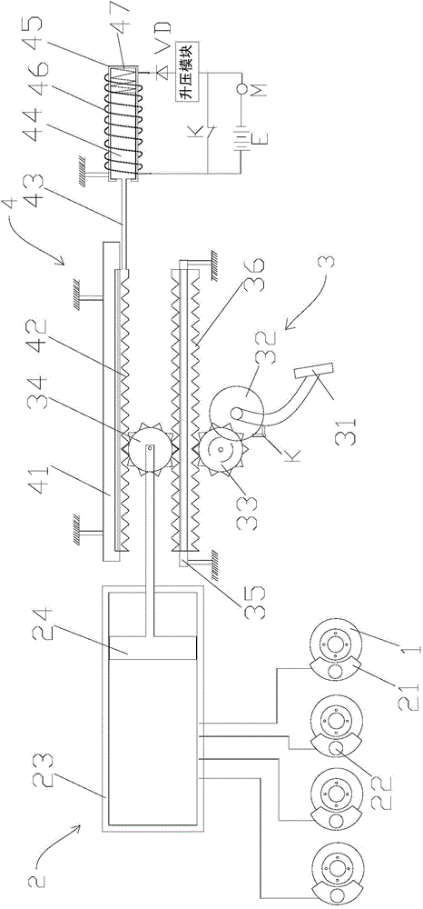
[0044] figure 2 A schematic structural diagram of the braking electric energy recovery subsystem of the present invention is shown.
[0045] like figure 2 As shown, the brake electric energy recovery subsystem includes a hydraulic brake mechanism 2 and a brake coordinating assembly 4 that cooperates with the hydraulic brake mechanism 2; when braking, the brake coordinating assembly 4 is suitable for generating The force acting opposite to the...
Embodiment approach
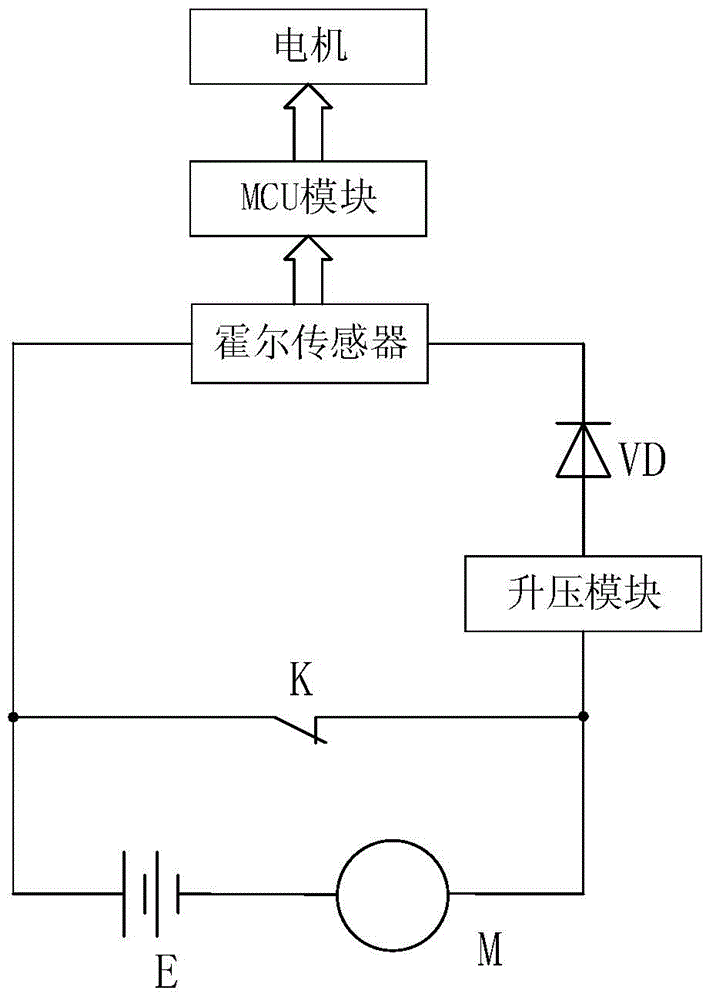
[0058] Specific implementation manner: the charging circuit includes a diode VD; the positive pole of the battery E is connected to one end of the electromagnetic coil 46, the other end of the battery coil is connected to the cathode of the diode VD, and the anode of the diode VD is connected to the boost voltage The output end of the module is connected, the input end of the boost module is connected to one end of the wheel drive motor M, the negative pole of the battery E is connected to the other end of the wheel drive motor M; the auxiliary switch is a normally closed switch, and the normally closed Both ends of the switch are respectively connected to the input end of the boost module and the positive pole of the storage battery E.
[0059] The unidirectional characteristic of the diode VD can effectively prevent the battery E from continuing to discharge the wheel drive motor M through the electromagnetic coil 46 after the normally closed switch is turned on; and the char...
PUM
 Abstract
Description
Claims
Application Information
 - R&D
- Intellectual Property
- Life Sciences
- Materials
- Tech Scout
- Unparalleled Data Quality
- Higher Quality Content
- 60% Fewer Hallucinations
Browse by: Latest US Patents, China's latest patents, Technical Efficacy Thesaurus, Application Domain, Technology Topic, Popular Technical Reports.
© 2025 PatSnap. All rights reserved.Legal|Privacy policy|Modern Slavery Act Transparency Statement|Sitemap|About US| Contact US: help@patsnap.com


