Fiber bragg grating array-based phase-sensitive optical time domain reflection device and method

A Bragg fiber, phase-sensitive optical time-domain technology, applied in measurement devices, using wave/particle radiation, and alarms that rely on interfering short-wavelength radiation, etc. Measurements, effects of high spatial resolution measurements

Active Publication Date: 2015-10-21
NANJING UNIV
View PDF10 Cites 57 Cited by
  • Summary
  • Abstract
  • Description
  • Claims
  • Application Information

AI Technical Summary

Problems solved by technology

[0005] The technical problem to be solved by the present invention is to overcome the deficiencies of the prior art, provide a phase-sensitive optical time-domain reflection device and method based on a fiber Bragg grating array, and solve the problem that the existing phase-sensitive optical time-domain reflection device cannot realize the quantification of optical fiber strain Measurement problems, both quantitative analysis and precise positioning

Method used


Image

  • Fiber bragg grating array-based phase-sensitive optical time domain reflection device and method
  • Fiber bragg grating array-based phase-sensitive optical time domain reflection device and method
  • Fiber bragg grating array-based phase-sensitive optical time domain reflection device and method

Examples


Embodiment 1

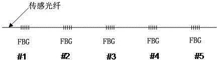
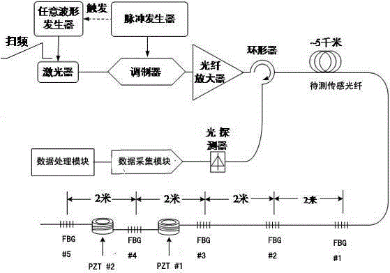
[0037] In this embodiment, the laser frequency adjustment module can adopt time-sweeping demodulation mode, such as figure 2 As shown, the laser frequency adjustment module uses an arbitrary waveform generator and a tunable laser as a light source with a line width of 3.7kHz and a wavelength of 1561.38nm; five FGBs with the same reflectivity of 1% are placed at the end of the sensing fiber , numbered in turn from #1 to #5, and the distance between two pairs is 2m to form a grating array. The signal-to-noise ratio and detection distance can be achieved; the reflection spectrum of the grating in the array should be as wide as possible, and the full-width half-maximum (FWHM) of the reflection spectrum should be at least >1nm; the spacing between the gratings in the array is equal, and the spacing determines the space that the device can reach resolution; the parameters of the fiber grating in the array are the same; even if the above-mentioned fiber grating with extremely weak r...

Embodiment 2

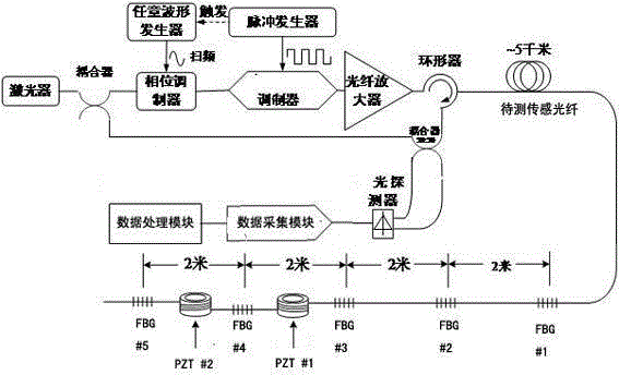
[0057] The difference between this embodiment and Embodiment 1 is that the frequency adjustment module in the device adopts the structure of partial overlapping time sweeping mode, such as image 3 As shown, the laser frequency adjustment module includes an arbitrary waveform generator and a phase modulator, and the arbitrary waveform generator controls the phase modulator to shift the frequency of the continuous light emitted by the light source.

[0058] The modulation process is as follows: a tunable laser is used as the light source, its line width is 3.7kHz, and its wavelength is 1561.38nm; 90% of the light passing through the coupler reaches the phase modulator, and after the laser exits, it passes through a 90:10 coupler, of which 10 % is used as a local oscillator light signal; a modulator with a high extinction ratio is applied to the continuous light output by the laser, and then converted into a detection pulse light with a pulse width of 150 ns, and the modulator su...

Embodiment 3

[0062] The difference between the embodiment of this device and the second embodiment is that the laser frequency adjustment module in the device adopts the structure of completely overlapping time sweep mode, such as Figure 4 As shown, the laser frequency adjustment module includes an arbitrary waveform generator and a phase modulator, and the arbitrary waveform generator controls the phase modulator to modulate the continuous light emitted by the light source.

[0063] The modulation process is as follows: the coherent detection method is selected, and the tunable laser is used as the light source. The linewidth is 3.7kHz and the wavelength is 1561.38nm; 90% of the light passing through the coupler reaches the phase modulator, and the laser passes through a 90 : 10 couplers, 10% of which are used as local oscillator optical signals; a high extinction ratio pulse modulator is applied to the continuous light output by the laser, and then converted into photodetection pulsed li...


PUM


Abstract

The invention discloses a fiber bragg grating array-based phase-sensitive optical time domain reflection device and method. The device includes a light source, a laser frequency adjustment module, a modulator, an optical fiber amplifier, a circulator, a sensing optical fiber, a light detector, a data acquisition module and a data processing module; the sensing optical fiber is provided with an optical fiber array formed by a plurality of FBGs (fiber bragg grating) which are arranged equidistantly; the laser frequency adjustment module is used for frequency adjustment of continuous light emitted by the light source; the continuous light is modulated by the modulator so as to form pulsed light; the optical fiber amplifier performs power amplification on the pulsed light; the sensing optical fiber is used for receiving and transmitting the pulsed light which has been subjected to power amplification; the light detector receives scattered light and reflected light; the scattered light and reflected light are acquired by the data acquisition module; and the data processing module generates interference signal frequency response spectrum and obtains the length variation quantity of the sensing optical fiber between two adjacent FBGs through processing. With the fiber bragg grating array-based phase-sensitive optical time domain reflection device and method of the invention adopted, strain quantitative detection can be realized, and high-spatial resolution measurement can be realized based on quantitative analysis.

Description

technical field [0001] The invention relates to a phase-sensitive optical time-domain reflection device and method based on a Bragg fiber grating array, and belongs to the field of distributed optical fiber sensing technology. Background technique [0002] Phase-sensitive Optical Time Domain Reflectometry (Φ-OTDR). It is a fully distributed optical fiber sensing technology with high sensitivity and full passive, which can continuously sense the spatial distribution and time change information of dynamic parameters such as strain and vibration on the transmission path. It can be used to detect extremely weak optical fiber vibrations, and is usually used for perimeter security intrusion detection and building structure health monitoring. [0003] Φ-OTDR is used for the sensing of optical fiber disturbance and temperature change, such as figure 1 For the structure shown, the location of the perturbation is obtained by measuring the time delay between the injected pulse and th...

Claims


Application Information

Patent Timeline
Patent Type & Authority Applications(China)
IPC IPC(8): G01H9/00G08B13/18
Inventor 张益昕张旭苹郭铮朱帆李建华刘品一
Owner NANJING UNIV
Why Eureka
Try Eureka