Method for directly obtaining martensite die steel through laser 3D printing technology

A 3D printing and martensite technology, which is applied in the field of laser 3D printing rapid manufacturing of directly obtained martensitic die steel, can solve the problems of high scrap rate, complex process and high cost, reduce brittleness, avoid traditional processes, mechanical Excellent performance

Active Publication Date: 2015-11-11
南京瑞德增域三维科技发展有限公司
View PDF10 Cites 36 Cited by
  • Summary
  • Abstract
  • Description
  • Claims
  • Application Information

AI Technical Summary

Problems solved by technology

[0007] The purpose of the present invention is to provide a method for directly obtaining martensitic die steel by using laser 3D printing technology to solve the problems of comple...

Method used


Image

  • Method for directly obtaining martensite die steel through laser 3D printing technology
  • Method for directly obtaining martensite die steel through laser 3D printing technology
  • Method for directly obtaining martensite die steel through laser 3D printing technology

Examples


Embodiment 1

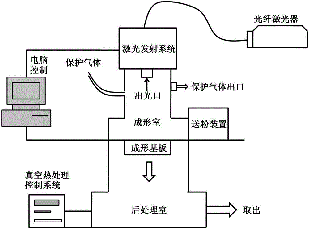
[0034] Such as figure 1 As shown, the method for directly obtaining martensitic die steel using laser 3D printing technology described in the present invention comprises the following steps:

[0035] (1) Establish the geometric model of the mold on the computer, use the slicing software to carry out layered discretization of the geometric model, and generate a scanning model from the two-dimensional geometric contour.

[0036] (2) Add Mn, Ni, and Cr powders of the same particle size and shape to the iron powder, the average particle diameter of the iron powder is 60 μm, and the mass percentages of Mn, Ni, and Cr powders added are 2.0%, 4.0%, and 1.2% respectively ; After mixing the metal powder evenly, put it into a drying oven for drying treatment for 8 hours.

[0037] (3) Fix the substrate horizontally on the forming cylinder, adjust the height of the horizontal substrate and the scraper to a suitable position, and ensure that the scraper can smoothly send the metal powder ...

Embodiment 2

[0046] The difference between this embodiment and the specific embodiment one is that the distribution ratio of each component in the metal powder and the laser process parameters in step (6) are changed, specifically:

[0047] The mass percentages of Mn, Ni, Cr powder added are 2.2%, 3.6%, 1.4% respectively

[0048] The laser power is set to 60W, the scanning speed is set to 400mm / s, and the laser line energy density η is 150J / m at this time. Others are the same as the first embodiment.

Embodiment 3

[0050] The difference between this embodiment and the first embodiment is that the distribution ratio of each component in the metal powder and the laser process parameters in step (6) are changed,

[0051] The mass percentages of Mn, Ni, Cr powder added are 2.1%, 4%, 1.3% respectively

[0052] The laser power is set to 80W, the scanning speed is set to 200mm / s, and the laser line energy density η is 400J / m at this time.

[0053] Others are the same as the first embodiment.


PUM

PropertyMeasurementUnit
Average particle sizeaaaaaaaaaa
Coefficient of frictionaaaaaaaaaa
Wear rateaaaaaaaaaa

Abstract

The invention provides a method for directly obtaining martensite die steel through a laser 3D printing technology. According to the method, a defined amount of Mn, Ni, Cr and other alloy elements are added to iron powder, and within a wide temperature range, martensite transformation is facilitated. The influence rules of laser linear energy density eta (the ratio between laser power and scanning speed) on the density, microscopic structure and mechanical property of an SLM forming part are analyzed, parameters of the laser 3D printing technology are optimized, and a mold of a complex structure in any shape is obtained. Moreover, the forming mold has high hardness, abrasion resistance and good impact toughness, and is better in performance than a mold manufactured in a traditional method. Accordingly, the method is particularly suitable for rapid forming of molds of a complex structure.

Description

technical field [0001] The invention belongs to the technical field of rapid mold manufacturing, in particular to a laser 3D printing rapid manufacturing method for directly obtaining martensitic mold steel. Background technique [0002] Mold is the main processing tool for manufacturing parts in machinery manufacturing, automobile manufacturing, aerospace, radio instrumentation, electrical appliances and other industrial sectors. The quality of mold directly affects the quality of processing technology, product accuracy and production cost. [0003] The traditional manufacturing methods of metal molds include traditional mechanical processing methods such as turning, clamping, milling, planing, and grinding. For the cold stamping die, during its service process, due to the relatively large deformation resistance of the processed material, the working part of the die bears a large compressive stress, bending force, impact force and friction force. Therefore, the main failur...

Claims


Application Information

Patent Timeline
IPC IPC(8): B22F3/105B22F3/24B33Y10/00
CPCY02P10/25
Inventor 顾冬冬陈洪宇戴冬华余冠群
Owner 南京瑞德增域三维科技发展有限公司
Why Eureka
Try Eureka