Measuring method and device of spectrometer while drilling for measuring oil and gas composition

A measurement method and spectrometer technology, applied in the field of optical systems, can solve the problems of unsystematic long-term stability performance testing of new devices, maximum operating temperature of 60-80°C, and high cost of quantum cascade lasers, etc., and achieve a wide natural operating temperature range. , low power consumption, small cross-section effect

Inactive Publication Date: 2018-05-25
CHINA UNIV OF PETROLEUM (EAST CHINA)
View PDF8 Cites 0 Cited by
  • Summary
  • Abstract
  • Description
  • Claims
  • Application Information

AI Technical Summary

Problems solved by technology

Both require grating dispersion and space separation, many peripheral supporting equipment, and large cross-section
There are defects in the technical implementation of the quantum cascade laser scheme: quantum cascade lasers are expensive and costly; the driving current is above 500mA, and the power consumption is large; the long-term stability performance test as a new device is not systematic; It is a far-infrared light source with a wavelength of 5 μ m or more, and the Raman scattering generated is a far-infrared signal with a longer wavelength, which is extremely challenging for the optical system and detection system
[0010] Laser-based modulated absorption spectroscopy technology has extremely high sensitivity, and is now developed by some international large companies such as GE, E+H, NeoMonitor, etc. and developed in the petrochemical field for online analyzers of trace gases in ppm or even ppb levels , but the maximum operating temperature of laser diodes and detectors used in the near-infrared and mid-infrared bands is 60-80°C. Even with the addition of a temperature adjustment module, the operating temperature can be increased by up to 30°C, which still cannot meet the requirements

Method used


Image

  • Measuring method and device of spectrometer while drilling for measuring oil and gas composition
  • Measuring method and device of spectrometer while drilling for measuring oil and gas composition
  • Measuring method and device of spectrometer while drilling for measuring oil and gas composition

Examples


Embodiment Construction

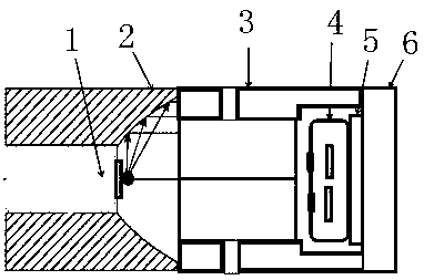
[0049] Accompanying drawing is a kind of specific embodiment of the present invention. This embodiment includes a parabolic reflector that collimates the luminous point of the light source 1, and is characterized in that a sampling gas chamber, a reference gas chamber and a detector with four channels and four independent thermopiles are arranged behind the reflector, each Each channel is equipped with a filter and a transmission window, and the detector 4 is installed on a semiconductor cooling chip 5 . There are four passages in the cavity 3 of the sample gas chamber and the reference gas chamber. The installation base 6 is the installation base for installing the analyzer, and is also the cooling channel for the cooling fin.

[0050] The light source 1 is installed in the parabolic reflector 2, and its luminous point is located at the focus of the parabolic reflector, so that the emitted light can be effectively emitted in parallel to achieve collimation. The gas chamber ...


PUM

PropertyMeasurementUnit
lengthaaaaaaaaaa
diameteraaaaaaaaaa

Abstract

The invention relates to a measuring method and device of a spectrometer while drilling for measuring oil and gas components. It includes a parabolic reflector for collimating the luminous point of the light source, and is characterized in that a sampling gas chamber and a reference gas chamber and a detector with four channels and four independent thermopiles are arranged behind the reflector, and each channel is equipped with one Filters and transmission windows, and detectors are installed on semiconductor cooling chips. This patent mainly has the following advantages: fast analysis speed; low analysis cost; good test reproducibility; online analysis, through the current mature downhole signal transmission technology; small size, especially small cross-section, easy to integrate into drilling while drilling In the equipment; low power consumption; the driving current of the new infrared radiation light source is only about 100mA, considering the pulse width modulation of 20‑50% duty cycle, the actual power is even lower.

Description

(1) Technical field [0001] The invention relates to an optical system, in particular to a measuring method and device of a spectrometer while drilling for measuring oil and gas components. (2) Background technology [0002] Measurement while drilling is the most important means to efficiently develop complex oil and gas reservoirs, which is in line with the future development trend of the industry. The measurement-while-drilling of oil and gas composition based on spectral technology can effectively solve the real-time online measurement of oil and gas composition in the process of oil and gas drilling, and provide a reliable basis for drilling decisions. Compared with many traditional technologies, spectroscopic technology has technical advantages such as simultaneous detection of multiple components, fast analysis speed, and selective reaction. This patent designs a high-temperature dedicated infrared spectrometer system for the high-temperature and high-pressure closed m...

Claims


Application Information

Patent Timeline
Patent Type & Authority Patents(China)
IPC IPC(8): E21B47/00G01N21/25
Inventor 季文海
Owner CHINA UNIV OF PETROLEUM (EAST CHINA)
Why Eureka
Try Eureka