Supercharge Your Innovation With Domain-Expert AI Agents!

Compression type braking and retarding system for automobile engine

A car engine, compression technology, applied in the direction of engine components, machines/engines, mechanical equipment, etc., can solve the problems of complex structure, large volume, heavy weight, etc., and achieve the effect of small volume, simple structure and light weight

Active Publication Date: 2015-12-16
莫嘉林
View PDF6 Cites 1 Cited by
  • Summary
  • Abstract
  • Description
  • Claims
  • Application Information

AI Technical Summary

Problems solved by technology

[0003] In order to overcome the shortcomings of the existing automobile engine compression brake retarder system, such as complex structure, large volume, heavy weight, and the system also needs to adjust the gap when installing or overhauling the engine to adjust the valve, etc., the present invention provides an automobile engine compression Braking retarding system, the system can timely provide engine braking retarding performance when the driver needs the engine to brake retarding,

Method used


Image

  • Compression type braking and retarding system for automobile engine
  • Compression type braking and retarding system for automobile engine
  • Compression type braking and retarding system for automobile engine

Examples


Embodiment Construction

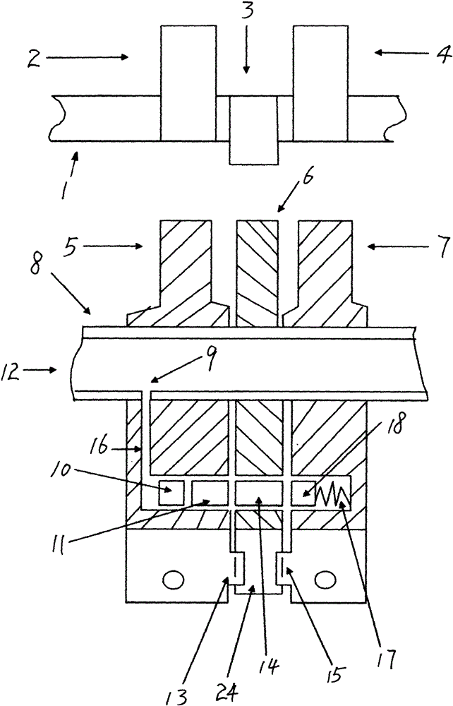
[0016] The automobile engine compression brake retarder system is composed of an overhead camshaft (1), a first exhaust valve rocker arm (5), a second exhaust valve rocker arm (7), a first adjusting screw (22), and a first exhaust valve rocker arm (7). Two adjustment screws (19), deflated rocker arm (6), positioning spring (26), timing piston (10), first synchronous piston (11), second synchronous piston (14), blocking piston (18), Blocking piston return spring (17), rocker shaft (8), oil pipe (32), solenoid valve (27), electric motor oil pump (33), pressure stabilizing valve (34), slow speed control circuit (31) form.

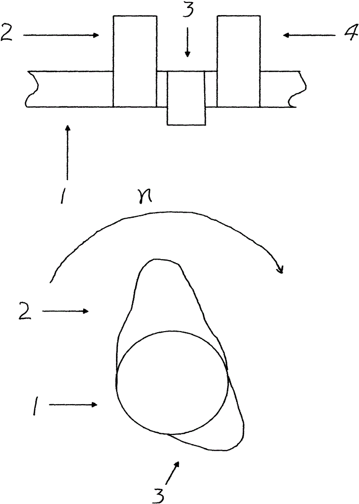
[0017] exist figure 1 , the camshaft (1) is provided with the first exhaust cam (2), the second exhaust cam (4) and the exhaust cam (3), and the rotation direction n indicates that the exhaust cam (4) is located near the end of the compression stroke corresponding position.

[0018] exist figure 2 Among them, the function of the first exhaust cam (2) and t...


PUM


Abstract

The invention relates to a compression type braking and retarding system for an automobile engine. When an automobile runs, a deflation rocking arm and exhaust valve rocking arms can be connected together to rock in good time through the system when a driver gives out a deceleration instruction, meanwhile, the engine stops fuel oil supply, the automobile is not in a neutral position, and a clutch is in a completely-engaged state, so that the exhaust valve rocking arms comply with drive of exhaust cams and also comply with drive of a deflation cam; an exhaust valve is opened in the exhaust stroke, the exhaust valve is also opened when a piston is close to an upper compression dead center, compressed air consuming inertial kinetic energy of the automobile is exhausted, the piston is barely pushed by the compressed air in the acting stroke, then the exhaust valve is closed soon after the acting stroke is started, and negative pressure is generated while the piston continues to move in the acting stroke so as to increase the motion resistance of the piston; the engine becomes an air compressor at the moment, and the inertial motion energy of the automobile is consumed through the compressed air.

Description

1. Technical field [0001] The invention relates to an automobile engine compression retarder system, which is simpler in structure, more compact and lighter in weight than the known automobile engine compression retarder system. 2. Background technology [0002] At present, the function of the known automobile engine compression brake retarder system is: when the automobile is running in inertia, the driving wheel drives the engine to run through the transmission system, and the engine consumes the inertial motion energy of the automobile through compressed air, thereby reducing the running speed or reducing Running acceleration. The current automobile engine compression brake retarding system uses hydraulic transmission to change the timing of the exhaust valve. When the engine piston runs to the compression top dead center, the exhaust valve is pushed to release the compressed air in the combustion chamber. Outside the cylinder, there is no compressed air to push the pist...

Claims


Application Information

Patent Timeline
IPC IPC(8): F01L13/06F01L1/34
Inventor 陈红莫嘉林
Owner 莫嘉林
Features
  • R&D
  • Intellectual Property
  • Life Sciences
  • Materials
  • Tech Scout
  • Unparalleled Data Quality
  • Higher Quality Content
  • 60% Fewer Hallucinations
Learn More