High-precision shaft part machining method based on multiple times of detection and compensation

A shaft part, multiple detection technology, applied in metal processing, metal processing equipment, metal processing mechanical parts, etc., can solve the effect of error analysis, compensation and correction, can not achieve sub-micron accuracy, does not consider high surface roughness, etc. problems, to achieve the effect of achieving measurement, avoiding offline inspection and re-installation of workpieces, and improving processing efficiency and processing accuracy

Active Publication Date: 2015-12-23
BEIJING SATELLITE MFG FACTORY
View PDF7 Cites 29 Cited by
  • Summary
  • Abstract
  • Description
  • Claims
  • Application Information

AI Technical Summary

Problems solved by technology

That is, the error term is measured first, and then the actuator of the machine tool itself is used for compensation. The compensation ability depends on the detection accuracy and the motion accuracy of the executive parts of the machine tool itself. After compensation, the straightness and positioning accuracy are generally reduced from tens of microns to the micron level , can not achieve sub-micron precision; and the use of additional error compensation system research is less, in "machine tool error signal separation and compensation technology research" using the method of additional giant magnetostrictive actuator and flexible hinge to the ball screw The positioning accuracy of the platform is compensated, using offline detection-open loop compensation, the compensation effect is reduced from ±15μm to ±8μm
However, the existing machine tool error compensation method uses one-time compensation, and there is no error analysis and further compensation correction for the effect after one-time compensation
[0005] For the processing of high-precision workpieces, there are many error sources that affect the machining accuracy of workpieces, including machine tool error detection and compensation, micro-displacement actuators, high-precision workpiece measurement, force deformation and thermal deformation of the processing technology system, processing procedures, and clamping methods And deformation analysis, cutting force deformation, tool selection and wear control, cooling and lubrication, etc. At present, there are considerable studies on the analysis of these single error sources, but the technology to quantitatively convert these error sources into machining workpiece errors has not yet been solved.
Moreover, the existing research mostly focuses on the research of single or several error sources, but based on the whole process of high-precision workpiece processing, that is, machine tool error detection-machine tool error compensation-workpiece processing arrangement-workpiece error detection-workpiece error simultaneous Compensation studies have not been reported
At the same time, the existing workpiece accuracy compensation technology mostly focuses on size and shape accuracy compensation, without considering the high surface roughness requirements

Method used


Image

  • High-precision shaft part machining method based on multiple times of detection and compensation
  • High-precision shaft part machining method based on multiple times of detection and compensation
  • High-precision shaft part machining method based on multiple times of detection and compensation

Examples


Embodiment Construction

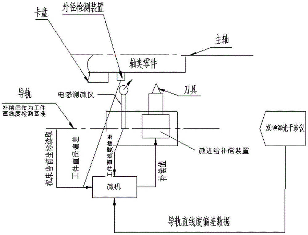
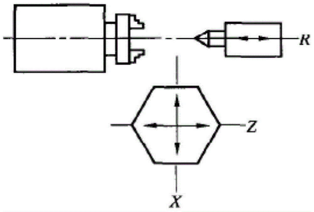
[0046] Such as figure 1 with figure 2 The processing system shown includes a microcomputer, a controller, a micro-feed compensation device, a walking board, a lathe guide rail, an inductance micrometer, a dual-frequency laser interferometer, an outer diameter detection device and shaft parts, and the Z axis is parallel to the processing guide rail , X-axis and Z-axis are perpendicular to the horizontal direction, the CNC lathe is 180CCN CNC lathe, the positioning error of the machine tool is 2μm, and the Z-axis of the CNC lathe is commonly used for strokes of 400mm to 190mm for shaft processing.

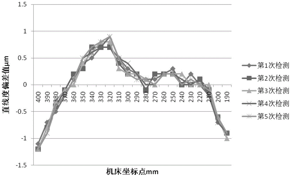
[0047] Step 1. Install the beam splitter of the dual-frequency laser interferometer on the extended end of the micro-feed compensation device, and fix the mirror on the machine tool. The CNC lathe moves along the Z guide rail at a constant speed from the coordinate 400mm to 190mm, and stops for 10 minutes at intervals of 10mm. Seconds, after the machine tool and the measuring syste...


PUM


Abstract

Provided is a high-precision shaft part machining method based on multiple times of detection and compensation. The deviation of straightness accuracy of a guide rail, deviation of straightness accuracy of a part and deviation of the size of the part are compensated with a micro-feeding compensation device as additional hardware aiming at a digital controlled lathe. A cubic spline function is established, two times of compensation is conducted on the deviation of straightness accuracy of the guide rail through an interpolation method, the compensated guide rail serves as a standard, the straightness accuracy of the part is detected, and compensation machining is conducted on the deviation of straightness accuracy of the part and the deviation of the size of the part through the micro-feeding compensation device, so that machining of high-size-precision and high-straightness-accuracy shaft parts is achieved. The actual machining precision of the lathe is higher than the maximum machining precision of the lathe, so that the requirement for machining precision of the part is met. The straightness accuracy and positioning precision of the compensated guide rail can achieve the submicron-order precision.

Description

technical field [0001] The invention relates to a processing method for shaft parts, in particular to a processing method for shaft parts based on error detection and compensation. Background technique [0002] With the development of technology, higher and higher requirements are put forward for the accuracy of various motion mechanisms. As the important executive components of the motion mechanism, the shafting parts have a direct impact on the motion accuracy of the mechanism such as straightness and dimensional accuracy. For example, in the defense industry, the gyroscope of the missile system directly affects its hit rate. For a 1kg gyro rotor, if its center of mass deviates from its symmetry axis by 0.5 μm, it will cause a range error of 100m and an orbit error of 50m. [0003] As the most commonly used processing equipment for shaft parts, CNC lathes have a direct impact on the machining accuracy of parts due to their guide rail straightness and positioning accuracy. ...

Claims


Application Information

Patent Timeline
Patent Type & Authority Applications(China)
IPC IPC(8): B23Q15/013B23Q15/12
CPCB23Q15/013B23Q15/12
Inventor 韩建超李茂伟樊晓霞张玉良王磊李娜杨三强路勇陆国栋周明
Owner BEIJING SATELLITE MFG FACTORY
Why Eureka
Try Eureka