Supercharge Your Innovation With Domain-Expert AI Agents!

Indirect Chain Straw Hot Air Stove

A technology of hot blast stove and chain row, which is applied to heating devices, air heaters, fluid heaters, etc., can solve the problems of large energy loss, insufficient heat exchange, and low degree of automation of flue heat pipes, and achieves easy maintenance and overall integration. The effect of compact structure and high safety

Active Publication Date: 2018-06-26
无锡市惠山区农机化技术推广服务中心 +1
View PDF7 Cites 0 Cited by
  • Summary
  • Abstract
  • Description
  • Claims
  • Application Information

AI Technical Summary

Problems solved by technology

There are also double-channel reverse air intake or staggered partitions in the middle of the air duct, which makes the hot air duct relatively longer, but generally speaking, the hot air duct basically crosses the flue heat pipe horizontally. The time on the outer wall of the flue heat pipe is short, the heat exchange is insufficient, the energy loss of the flue heat pipe is large, and there is no reusing mechanism for the air at the flue outlet, so there are common problems of high energy consumption, low thermal efficiency, and serious waste of energy
In addition, there are also heat exchangers designed with hierarchical serpentine heat pipe structure and reverse composite hot air channel structure. The flow channel is long, hot (air) gas and flue gas go their own way, reverse heat exchange, and automatic temperature control are new high-efficiency and energy-saving. Atmospheric pressure hot blast stoves are mainly suitable for multi-fuel energy such as coal and wood. Although the thermal efficiency can be increased to more than 75%, the heat supply is small, the structure is more complicated, the cost is high, and the degree of automation is low.

Method used


Image

  • Indirect Chain Straw Hot Air Stove
  • Indirect Chain Straw Hot Air Stove
  • Indirect Chain Straw Hot Air Stove

Examples


Embodiment Construction

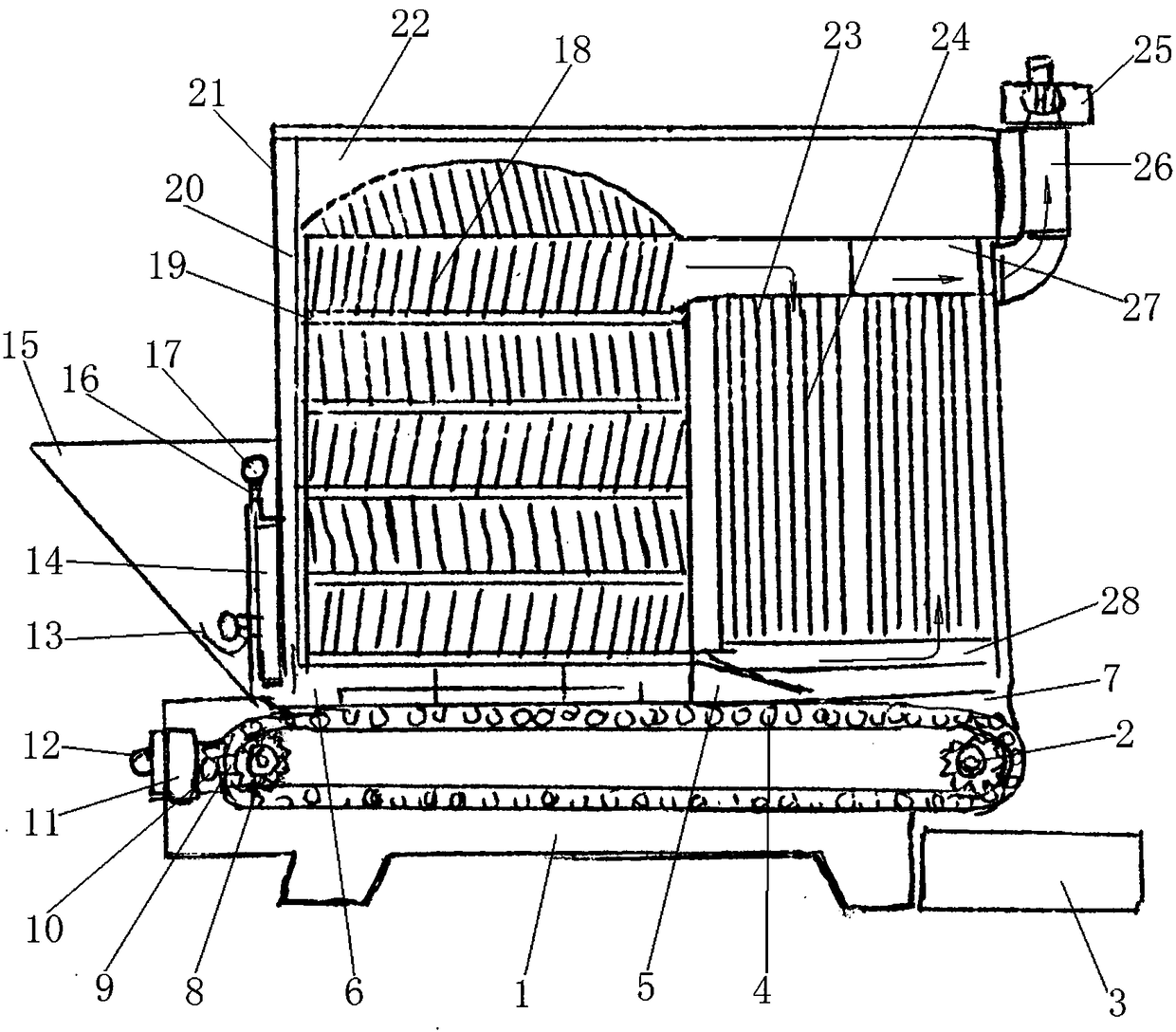
[0037] Refer to attached Figure 1~6 The indirect chain row straw hot blast stove consists of a furnace body, a heat dissipation fin type furnace device, a spiral heat dissipation fin type heat pipe group device, a feed adjustment and backfire prevention device, an automatic chain row device, a blower 30, an induced draft fan 34, Flue fan 25 forms.

[0038] The furnace body includes a heat exchange chamber 22, a frame 21, a base 1, a furnace door 31, a blast air inlet adjustment handle, an air damper 29, a heat insulation sealing plate 20, an air inlet 33, and an air inlet mesh plate 32. A frame 21 is connected to the top of the base 1 .

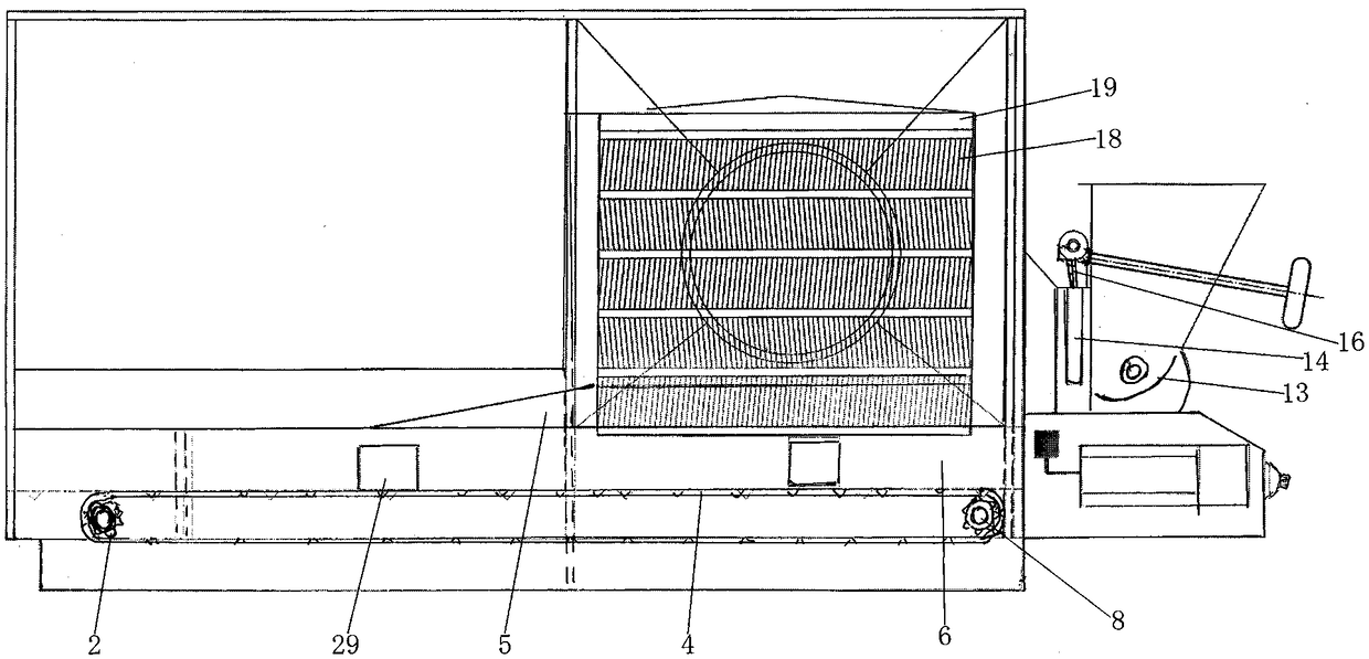
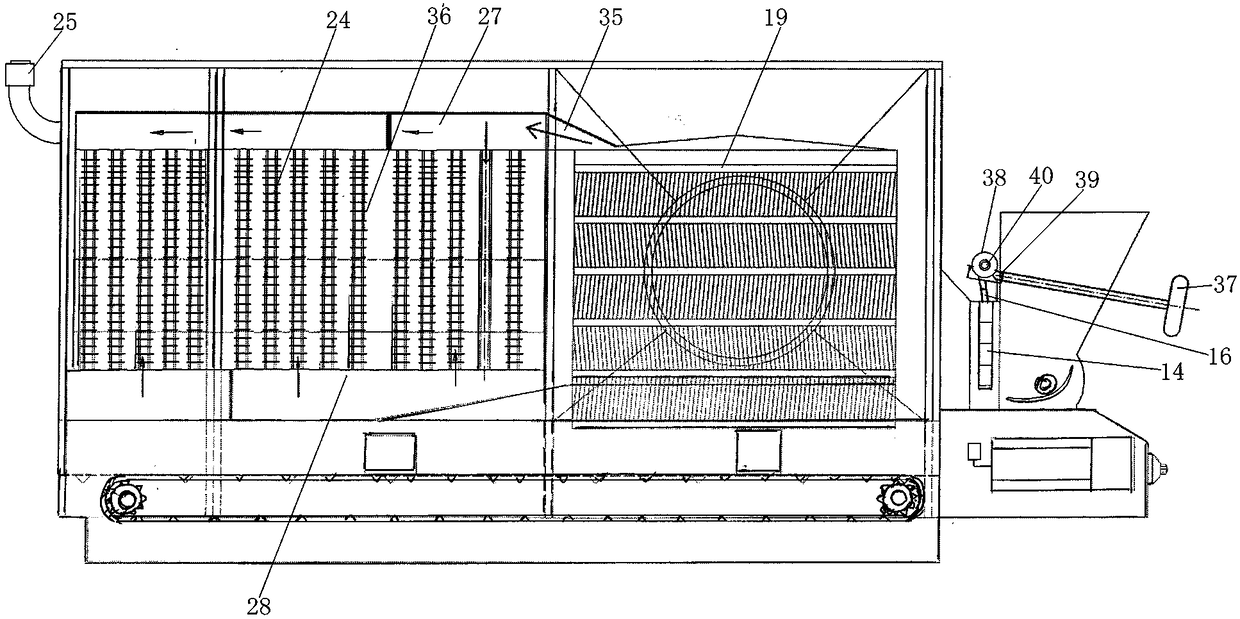
[0039] The heat dissipation fin type furnace device includes a furnace chamber 19, heat dissipation fins 18, feed passage 6, auxiliary combustion passage 5, and flue gas transition passage 35. Furnace hearth 19 is installed on the front portion of base 1, and the diameter of fire hearth 19 can be between 1.2~2m depending on the size of fur...


PUM


Abstract

The invention relates to an indirect chain-grate type straw hot air stove, and belongs to a device for carrying out heat conduction through straw fuel combustion. Clean hot air drying media can be provided for existing drying devices to dry grain, seeds and agricultural and sideline products, heat can be supplied to greenhouses in high-efficiency facility agriculture, and a hot source and the like can also be supplied to industrial materials. The indirect chain-grate type straw hot air stove is composed of a stove body, a cooling fin type stove exergy device, a spiral cooling fin type heat tube set device, a feeding adjusting and backfire preventing device, an automatic chain grate device, an air blower, an induced draft fan and a flue draught fan. The stove body comprises a heat exchange chamber, a rack, a base, a stove door, an air-blowing and air-inlet adjusting handle, an adjusting air door, a heat isolation sealing plate, an air inlet and an air inlet net plate. The cooling fin type stove exergy device comprises a hearth, cooling fins, a feeding channel, an auxiliary combustion channel and a smoke transition channel. The spiral cooling fin type heat tube set device comprises spiral cooling fin heat exchange tube sets, an upper flue flow dividing cavity, a lower flue flow dividing cavity and a flue draught fan connector.

Description

technical field [0001] The invention relates to an indirect chain row straw hot air stove, which belongs to a kind of equipment that utilizes straw fuel combustion for heat conduction, specifically for indirect heat exchange and heat transfer, and can provide clean hot air for existing drying equipment. Drying medium, drying grain, seeds and agricultural by-products, can provide heating for greenhouses in high-efficiency facility agriculture, and can also provide heat sources for industrial materials. Background technique [0002] Most of the various straw hot blast stoves currently in use have defects such as low thermal efficiency, poor smoke and dust removal, and low degree of automation. First of all, the design of the straw hot blast stove is not ideal in terms of heat exchange structure, flow rate, flow direction, etc., and there are generally problems such as low thermal efficiency of only about 70%, insufficient heat exchange and combustion, etc., resulting in large ...

Claims


Application Information

Patent Timeline
Patent Type & Authority Patents(China)
IPC IPC(8): F24H3/06F26B23/02F24H9/00
Inventor 顾靖峰王钰李建南周庆华周翔陈利江包锡忠沈叶红
Owner 无锡市惠山区农机化技术推广服务中心
Features
  • R&D
  • Intellectual Property
  • Life Sciences
  • Materials
  • Tech Scout
  • Unparalleled Data Quality
  • Higher Quality Content
  • 60% Fewer Hallucinations
Learn More