Method for compositely welding aluminum alloy in TIG welding manner and MIG welding manner alternately

A composite welding and aluminum alloy technology, which is applied in welding equipment, welding/welding/cutting items, arc welding equipment, etc., can solve the problems of poor weld formation, complicated welding equipment, and low welding efficiency, and achieve the reduction of tungsten electrodes Burning loss, automatic welding, and high welding efficiency

Inactive Publication Date: 2016-01-06
HARBIN INST OF TECH
View PDF4 Cites 6 Cited by
  • Summary
  • Abstract
  • Description
  • Claims
  • Application Information

AI Technical Summary

Problems solved by technology

[0011] The present invention aims to solve the problems of low welding efficiency, poor weld formation, complicated welding equipment, unstable process, poor flexibility and high cost in the existing aluminum alloy welding method, and provides an aluminum alloy TIG and MIG alternate compound welding method

Method used


Image

  • Method for compositely welding aluminum alloy in TIG welding manner and MIG welding manner alternately
  • Method for compositely welding aluminum alloy in TIG welding manner and MIG welding manner alternately

Examples


specific Embodiment approach 1

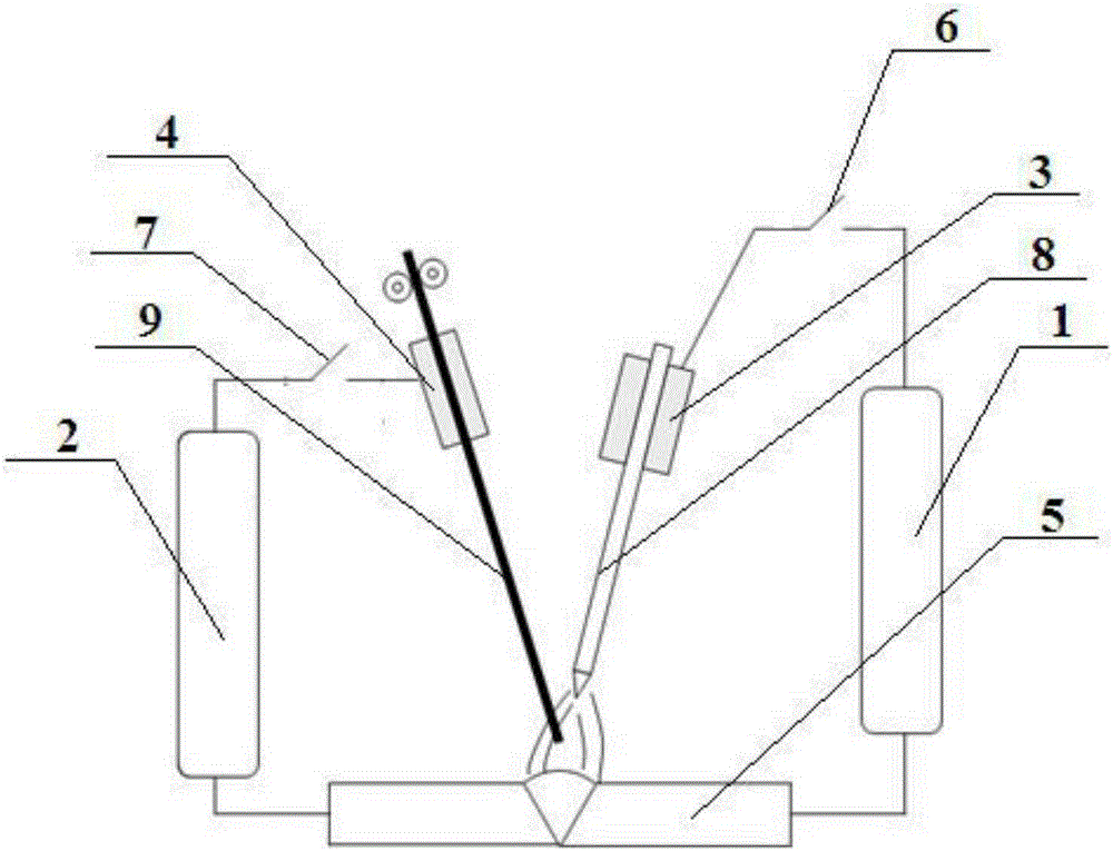
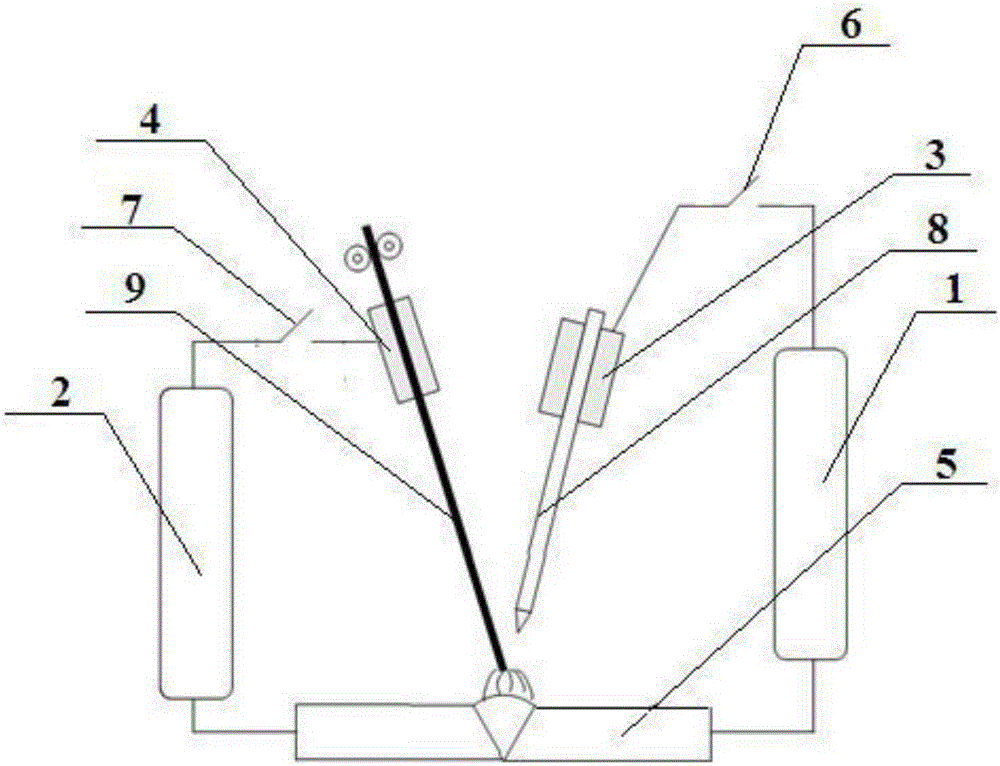
[0018] Specific implementation mode one: as figure 1 and figure 2 As shown, in this embodiment, an aluminum alloy TIG and MIG alternate composite welding method of the present invention is specifically carried out according to the following steps:

[0019] Connect the positive output end of the constant current TIG welding power source 1 to the workpiece 5 to be welded, connect the negative output end of the constant current TIG welding power source 1 to the tungsten electrode clamp 3, and clamp the TIG welding torch 8 on the tungsten electrode clamp 3. The gas shield on the side wall of the TIG welding torch 8 is provided with a melting electrode welding wire; the positive output terminal of the constant voltage MIG welding power supply 2 is connected to the melting electrode clamp 4, and the MIG welding torch 9 is clamped on the melting electrode clamp 4. The negative output terminal of the high-voltage MIG welding power supply 2 is connected to the workpiece 5 to be welde...

specific Embodiment approach 2

[0021] Specific embodiment two: the difference between this embodiment and specific embodiment one is: the nozzle of the TIG torch 8 is provided with a shielding gas channel, the shielding gas is a mixture of Ar and He or Ar; the shielding gas The feeding rate is 10~15L / min. Others are the same as the first embodiment.

specific Embodiment approach 3

[0022] Embodiment 3: This embodiment differs from Embodiment 1 or Embodiment 2 in that: the tungsten electrode of the TIG welding torch 8 and the melting electrode of the MIG welding torch 9 form an included angle of 5°-30°. Others are the same as those in Embodiment 1 or 2.


PUM


Abstract

The invention relates to a method for compositely welding an aluminum alloy in a TIG welding manner and a MIG welding manner alternately. The method disclosed by the invention aims to solve the problems that a conventional aluminum alloy welding method is low in welding efficiency, poor in weld-seam formation, complicated in welding equipment, unstable in process, poor in flexibility, and high in cost. The method comprises the following steps: the output end of the positive pole of a constant-current TIG welding power source is connected with a workpiece to be welded; the negative pole of the constant-current TIG welding power source is connected with a tungsten electrode clamp; a TIG welding gun is clamped on the tungsten electrode clamp; a melting-electrode welding wire is arranged in a gas protection sleeve on the side wall of the TIG welding gun; the positive pole of a constant-voltage MIG welding power source is connected with a melting-electrode clamp; a MIG welding gun is clamped on the melting-electrode clamp; the negative pole of the constant-voltage MIG welding power source is connected with the workpiece to be welded; through an IGBT switch, the constant-current TIG welding power source and the constant-voltage MIG welding power source are controlled to be alternately switched on and off, so that welding is realized. The method disclosed by the invention is used for welding the aluminum alloy.

Description

technical field [0001] The invention relates to an aluminum alloy TIG and MIG alternate composite welding method. Background technique [0002] With the rapid development of the manufacturing industry and the continuous improvement of welding technology, welded structures have been widely used. Aluminum alloy has good corrosion resistance, electrical conductivity, thermal conductivity and high specific strength, and is widely used in industrial fields such as automobile manufacturing, shipbuilding, national defense and aerospace, and container manufacturing. Therefore, aluminum alloy welding technology is increasingly valued. [0003] There are several difficulties in welding aluminum alloys: severe softening of welded joints, low strength coefficient, and refractory Al on the surface. 2 o 3 Oxide film requires a welding process with high power density; it is easy to produce defects such as pores and thermal cracks; the linear expansion coefficient is large, and welding de...

Claims


Application Information

Patent Timeline
IPC IPC(8): B23K9/16B23K9/23B23K103/10
CPCB23K9/164B23K9/23B23K2103/10
Inventor 高洪明王世博
Owner HARBIN INST OF TECH
Why Eureka
Try Eureka