Sulfur Recovery Process with Low Sulfur Emissions

A technology of sulfur recovery and sulfur discharge, applied in the direction of sulfur preparation/purification, etc., which can solve problems such as polluting the environment, difficult unloading, and limited facilities

Active Publication Date: 2018-05-08
山东迅达化工集团有限公司
View PDF2 Cites 0 Cited by
  • Summary
  • Abstract
  • Description
  • Claims
  • Application Information

AI Technical Summary

Problems solved by technology

[0011] C. Multiple replacements of catalytic oxidation adsorption desulfurizers in the process bring more hidden dangers of safety and environmental pollution
[0012] After the catalytic oxidation adsorption desulfurizer loaded in the adsorption desulfurization tower is saturated or penetrated, it needs to be unloaded and replaced with a new catalytic oxidation adsorption desulfurizer, so there is a problem of regular replacement of the catalyst frequently; when the agent is unloaded, the upper desulfurizer bed The layer often has agglomeration, which is difficult to unload, and the H physically adsorbed in the upper desulfurizer bed 2 S is emitted, there is an obvious odor, and the environment of the unloading site is poor. If proper treatment is not carried out, H will still be emitted during storage and transportation. 2 S, SO 2 odor, pollute the environment, and also affect the safety of operators; the unloaded waste desulfurizer contains more than 20% (mass) of sulfur, and there is a danger of flammability during storage and transportation, and SO 2 It will also cause environmental pollution; in the process of waste agent treatment, the processing factory is often small in scale and limited in facilities, which is likely to cause serious environmental pollution, and the sulfur contained in the waste agent cannot be effectively utilized.

Method used


Image

  • Sulfur Recovery Process with Low Sulfur Emissions
  • Sulfur Recovery Process with Low Sulfur Emissions
  • Sulfur Recovery Process with Low Sulfur Emissions

Examples


Embodiment 1

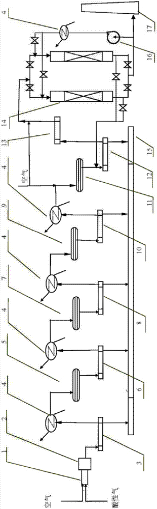
[0054] A set of 50,000 tons / year sulfur recovery unit in the refinery, including sequentially connected combustion furnace, primary Claus reactor, secondary Claus reactor, selective hydrogenation reduction reactor, selective oxidation reaction device and two adsorption desulfurization towers that can be connected in series and parallel, and the upper part of the first-stage Claus reactor is filled with Fe 2 o 3 / Al 2 O deoxidation protection type sulfur recovery catalyst 15m 3 , the lower part is filled with TiO 2 Sulfur recovery catalyst 25m 3 ; The upper part of the secondary Claus reactor is filled with Fe 2 o 3 / Al 2 o 3 Deoxidation protection type sulfur recovery catalyst 15m 3 , the lower part is filled with TiO 2 / Al 2 o 3 Sulfur recovery catalyst 25m 3 ; Selective hydrogenation reduction reactor filled with CoO-MoO 3 / Al 2 o 3 Selective reduction of SO 2 Catalyst 20m 3 , the selective oxidation reactor is filled with Fe 2 o 3 / SiO 2 selective oxidat...

Embodiment 2

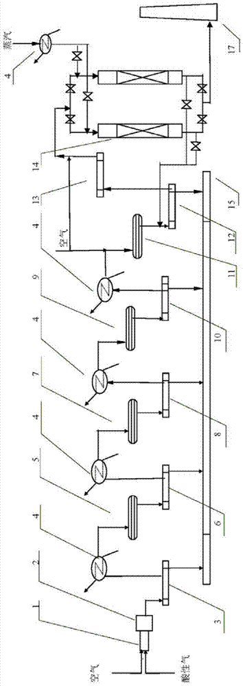
[0069] A 30,000-ton / year sulfur recovery unit in a methanol plant, including sequentially connected combustion furnaces, primary Claus reactors, secondary Claus reactors, selective hydrogenation reduction reactors, selective oxidation reactions device and two adsorption desulfurization towers that can be connected in series and parallel, and the upper part of the first-stage Claus reactor is filled with Fe 2 o 3 / Al 2 O deoxidation protection type sulfur recovery catalyst 12m 3 , the lower part is filled with TiO 2 Sulfur recovery catalyst 20m 3 ; The upper part of the secondary Claus reactor is filled with Fe 2 o 3 / Al 2 o 3 Deoxidation protection type sulfur recovery catalyst 12m 3 , the lower part is filled with TiO 2 Sulfur recovery catalyst 20m 3 ; Selective hydrogenation reduction reactor filled with CoO-MoO 3 / Al 2 o 3 Selective reduction of SO 2 Catalyst 15m 3 , the selective oxidation reactor is filled with Fe 2 o 3 / SiO 2 selective oxidation of H 2...


PUM


Abstract

The invention provides a low-sulfur emission sulfur recovery process, which includes sequentially connecting a combustion furnace, a primary Claus reactor, a secondary Claus reactor, a selective hydrogenation reduction reactor, and a selective oxidation reactor And two adsorption desulfurization towers that can be connected in series and parallel; through proper selection of catalysts and desulfurizers, and precise control of process conditions in each step, the total sulfur content of the process exhaust gas is SO2≤10mg / m3. After the desulfurization agent penetrates, use inert gas at 250-300°C for in-situ thermal regeneration, and the regenerated outlet gas returns to the combustion furnace, the condenser after the combustion furnace, the condenser after the first-stage Claus reactor, and the second-stage Claus reactor The condenser after the reactor, the condenser after the selective hydrogenation reduction reactor, or the condenser after the selective oxidation reactor, recovers elemental sulfur and sulfides such as H2S and SO2 in the regeneration gas, and regenerates the desulfurization tower During the period, the total sulfur content of the exhaust tail gas is SO2≤10mg / m3. The low-sulfur emission sulfur recovery process of the present invention has the advantages of low sulfur emission, long-term operation of the desulfurizer, large desulfurization amount, less replacement times, and low cost.

Description

technical field [0001] The invention relates to a sulfur recovery process, in particular to a low sulfur emission sulfur recovery process. Background technique [0002] During petrochemical, coal chemical, and coal gasification processes, part of the sulfur contained in raw materials is usually converted into H 2 S, separated to form H 2 Acid gas with high S content, the acid gas is generally treated by sulfur recovery process, H 2 S is converted to elemental sulfur as much as possible. certain high H 2 During the purification process of natural gas with S content, the separation of H 2 The acid gas formed by S should also be converted into elemental sulfur as much as possible through the sulfur recovery process. [0003] In the operation process of the sulfur recovery unit, there are also two problems of emptying tail gas and solid waste. The tail gas evacuated through the chimney, of which, SO 2 Concentration is a continuous monitoring item, although the upper limit...

Claims


Application Information

Patent Timeline
Patent Type & Authority Patents(China)
IPC IPC(8): C01B17/04
Inventor 胡文宾王强杨金帅
Owner 山东迅达化工集团有限公司
Why Eureka
Try Eureka