Vacuum-energy-storage-type launching catapult for fixed-wing aircraft

An aircraft take-off and energy storage technology, applied in the direction of launching/dragging transmissions, etc., can solve problems such as short maintenance cycle, uneven thrust, and difficult maintenance work, and achieve low requirements for manufacturing materials, increase service life, and make full use of effect of space

Inactive Publication Date: 2016-02-10
王振川
View PDF6 Cites 4 Cited by
  • Summary
  • Abstract
  • Description
  • Claims
  • Application Information

AI Technical Summary

Problems solved by technology

Its main disadvantages are: the carrier-based aircraft must take off against the strong wind, which is easily disturbed by the weather, and the aircraft carrier consumes a lot of energy to create a strong headwind; the carrier-based aircraft takes off for a long time, which makes it difficult to form a fleet; The full weight of the bombs takes off, resulting in a short range and low combat efficiency; and the most deadly thing is that in the context of modern warfare increasingly relying on system confrontation, the inability of carrier-based fixed-wing early warning aircraft and aerial refueling aircraft to take off in this way will greatly affect the Affecting the combat effectiveness of aircraft carriers
But the steam catapult has many other disadvantages: 1. It consumes a lot of fresh water and energy
2. The heat insulation and safety issues of storage and transportation of high-temperature and high-pressure steam are prominent
The use of heat insulation materials will occupy a large space, and absolute heat insulation does not exist, and the heat emitted will deteriorate the living environment of the crew; while the high-temperature and high-pressure steam storage tanks and pipelines are like ticking time bombs in wartime
3. The system is complex, the maintenance period is short, and maintenance is difficult. For example, the sealing rubber strip of the open cylinder seam and the sealing lubricating oil are easily deteriorated under high temperature and high pressure.
4. The thrust is extremely uneven during the ejection process, and the peak overload during the start-up period can reach 6g, which will cause sudden impact on the aircraft structure, greatly shorten its service life, and have adverse effects on the health of the pilots
5. The system needs to be "warmed up" for a long time before ejection
Since the outside world knows little about it, the actual application effect remains to be seen. We assume that the United States has overcome most of the shortcomings and deficiencies of the steam catapult in the development of the electromagnetic catapult. The technical difficulty is still worthy of our reference: 1. The United States has spent nearly 30 years on electromagnetic catapults and more than 3 billion US dollars
2. Cooling problem
The permanent magnet of the electromagnetic catapult is relatively sensitive to temperature. The critical temperature of demagnetization is between 100 and 200 degrees Celsius. The ejection process only takes 2 to 3 seconds. It is not easy to take away the heat generated by electromagnetic induction in such a short time. Otherwise, the life of the catapult will be greatly shortened
3. The main components of the electromagnetic catapult are easily damaged by moisture. So far, the United States has only conducted experiments on land. It is still unknown whether it can be applied to the high-salt and high-humidity environment at sea for a long time, at least the maintenance work is not easy.
4 Since the magnet of the electromagnetic catapult is slotted, it will generate strong electromagnetic radiation. In order to prevent the electromagnetic equipment of the aircraft and aircraft carrier from being disturbed, shielding electromagnetic radiation is also a difficult task
In order to obtain air dominance in the southern part of the South China Sea, it is a good way to fill in reefs and build an airport, but to fill in a standard airport, the workload will be unimaginable, and the investment will be huge

Method used


Image

  • Vacuum-energy-storage-type launching catapult for fixed-wing aircraft
  • Vacuum-energy-storage-type launching catapult for fixed-wing aircraft

Examples


Embodiment Construction

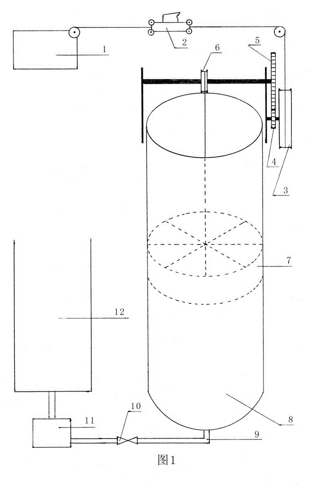
[0016]First, calculate the relevant data of the embodiment. For the convenience of calculation, the value of atmospheric pressure is 1kg / cm^2. After conversion, the pressure per square meter is 10 tons; the acceleration of gravity g is 10m / s; the weight of the piston is 9 tons through the counterweight, and its gravity is assumed to be exactly Offset the friction and other resistance of the system during ejection; the diameter of the vacuum cylinder is 6 meters, and the effective stroke of the piston is 11 meters. Then the pressure area of ​​the piston is 3.14x3^2=28.26 square meters, and the atmospheric pressure is 28.26x10=282.6 tons, which can be used for ejection. . After 9 times the acceleration from the small cable pulley to the large cable pulley, the net pulling force of the towing aircraft is 282.6 / 9=31.4 tons, and the towing distance is 11x9=99 meters. This distance can be increased by raising the oil level of the vacuum cylinder. Scaled down to accommodate ejectio...


PUM


Abstract

The invention relates to a vacuum-energy-storage-type launching catapult for a fixed-wing aircraft. The vacuum-energy-storage-type launching catapult is formed through sequentially connecting an electric winch, a trailer wagon, a speed transformation, a cable winding pulley, a large-diameter piston, a large-caliber vacuum cylinder, an oil pump, an oil storage tank and the like. The electric winch draws the piston to slowly rise to an upper dead point from a lower dead point under the deceleration of the speed transformation, so as to enable the interior of the vacuum cylinder to reach a completely-vacuum state and complete energy storage; the piston enables the trailer wagon to drive the aircraft to rapidly advance and launch through the acceleration of the speed transformation under the propulsion of atmospheric pressure and self-gravity, so as to complete catapult. Data related to specific embodiments of the invention are as follows: the catapult traction distance is 99 meters, the constant net traction force is 31.4 tons, the energy storage power is 600kw, the energy storage time is 60 seconds, the minimum requirements of a power supply on power is 800kw, the power consumption for catapult of one aircraft is lower than 20 kilowatt-hours, the gross weight of the catapult is lighter than 60 tons, and a system main body, i.e., the large-caliber vacuum cylinder has the height of 126 meters and the volume of 465 cubic meters. The vacuum-energy-storage-type launching catapult has the most principal features of uniformity in acceleration, little heat generation, low energy consumption, electrification, light weight and few systems.

Description

Technical field [0001] The invention relates to a take-off catapult for a fixed-wing aircraft, in particular to a take-off catapult for a fixed-wing aircraft using vacuum energy storage. It is suitable for catapult takeoff of fixed-wing aircraft on aircraft carriers, large amphibious assault ships and island reef airports. Background technique [0002] Since the birth of the aircraft carrier a hundred years ago, taking off fixed-wing aircraft on its narrow deck space has been a worldwide problem. In order to solve this problem, all major aircraft carrier countries have invested a lot of manpower and material resources to varying degrees. Through continuous research and exploration, a variety of carrier-based aircraft take-off catapults or auxiliary take-off devices have been developed, such as drop-weight type, flywheel type, spring slide type, rocket-assisted type, hydraulic type, and pneumatic type. , gunpowder type, electric type, etc. However, with the increase in siz...

Claims


Application Information

Patent Timeline
Patent Type & Authority Applications(China)
IPC IPC(8): B64F1/06
Inventor 王振川
Owner 王振川
Why Eureka
Try Eureka