Constructed wetland blocking monitoring device, and preparation method and application thereof

A technology for artificial wetlands and monitoring devices, which is applied in the direction of measuring devices, sampling devices, biological treatment devices, etc., to achieve the effects of simple preparation methods, avoiding aggravated clogging tendency, and convenient use

Inactive Publication Date: 2016-02-24
INST OF AQUATIC LIFE ACAD SINICA
View PDF9 Cites 2 Cited by
  • Summary
  • Abstract
  • Description
  • Claims
  • Application Information

AI Technical Summary

Problems solved by technology

The artificial wetland clogging monitoring device prepared by this method can be made by using ordinary PVC pipes, The inner and outer cylinders were designed during the preparation of the device. This design solves the disadvantage that the current wetland operation status can only be known through water quality. The inner cylinder can lift the wetland at any time, and the internal state of the wetland can be observed during operation, which is conducive to timely judging whether the wetland has a clogging tendency ; The gap between the

Method used


Image

  • Constructed wetland blocking monitoring device, and preparation method and application thereof
  • Constructed wetland blocking monitoring device, and preparation method and application thereof
  • Constructed wetland blocking monitoring device, and preparation method and application thereof

Examples


Example Embodiment

[0039] Example 1:

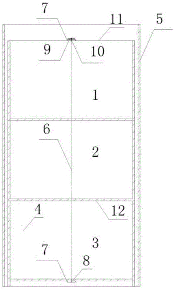
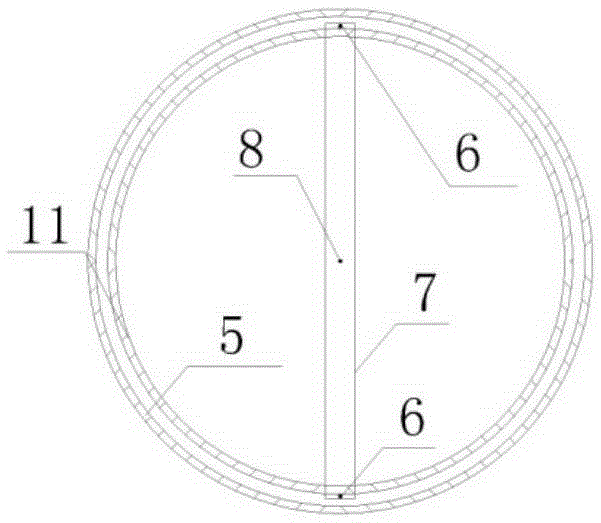
[0040] according to figure 1 , figure 2 It can be seen that a constructed wetland blockage monitoring device includes an inner upper cylinder 1, an inner middle cylinder 2, an inner lower cylinder 3, a matrix 4, an outer cylinder 5, a stainless steel fixing screw rod 6, a stainless steel sheet 7, a fixing nut 8, and a handle 9. , The ring fixing nut 10, the inner cylinder 11, and the fixed permeable plate 12. The connection relationship is: the inner upper cylinder 1, the inner middle cylinder 2, the inner lower cylinder 3 are fixed with a fixed permeable plate 12 respectively, and the inner middle cylinder 2 is aligned with the inner lower cylinder 3 and placed on it, and the inner upper cylinder 1 is right. Align the inner-middle layer cylinder 2 and place it on it. The inner cylinder 11 is composed of three parts: the inner upper cylinder 1, the inner middle cylinder 2, and the inner lower cylinder 3. Both sides of the inner cylinder 11 are fixed and cla...

Example Embodiment

[0048] Example 2:

[0049] A method for preparing a device for monitoring clogging of a constructed wetland. The steps are as follows:

[0050] A. Preparation of monitoring device:

[0051] 1) Prepare inner upper cylinder 1, inner middle cylinder 2, inner lower cylinder 3 (the preparation method is the same), using PVC control, the height can be adjusted according to demand, the bottom of the cylinder is fixed with a permeable plate full of small holes, permeable plate and cylinder A small hole is evenly punched on the wall every 0.9 or 1 or 1.1 cm, and the hole diameter can be adjusted as required.

[0052] 2) Prepare the outer cylinder 5, the outer cylinder 5 is 5cm higher than the inner cylinder, and the outer diameter is 5cm larger than the inner cylinder. The cylinder wall is evenly punched with a small hole every 0.9 or 1 or 1.1 cm.

[0053] B. Fill the substrate 4, select the substrate 4 consistent with the constructed wetland where the device is used, and the inner cylinder 11 ...

Example Embodiment

[0055] Example 3:

[0056] The application of a monitoring device in the blockage of constructed wetland, the steps are:

[0057] 1. The monitoring device is pre-buried, and the outer cylinder is buried in the preset point, which can be buried in the wetland surface 30 or 35 or 40 or 45cm. Place the inner cylinder in the middle of the outer cylinder, and after the device is buried, the wetland water level is required to be exactly below the upper cylinder of the device.

[0058] 2. Wetland monitoring, according to requirements, insert electrodes between the inner and outer cylinders to monitor the basic environmental parameters of wetland operation in real time, such as dissolved oxygen, redox potential, pH, etc.

[0059] 3. Collect the blockages. According to the requirements, one month after the device is buried in the wetland, the inner cylinder is raised, the upper fixing nut is unscrewed, the stainless steel sheet at the top is removed, the stainless steel fixing threaded rods on...


PUM

PropertyMeasurementUnit
The inside diameter ofaaaaaaaaaa
Apertureaaaaaaaaaa

Abstract

The invention discloses a method and device for strengthening denitrification by coupling an upward vertical flow constructed wetland with a microbial electrolysis cell. The method comprises the steps: A, water is uniformly distributed at the bottom of a system, and wastewater rises in a flow pushing manner along a bottom non-conductive filler layer firstly; B, the wastewater flows into an anode conductive filler layer; C, followed by, the wastewater flows into a non-conductive filler isolation layer which is a separator between a cathode conductive filler layer and the anode conductive filler layer; D, the wastewater flows into the cathode conductive filler layer, and nitrate nitrogen is subjected to autotrophic denitrification to be removed; and E, the wastewater flows out through a water draining pipe in an upper non-conductive filler layer. The anode conductive filler layer is connected with the non-conductive filler isolation layer and the bottom non-conductive filler layer, the cathode conductive filler layer is connected with the upper non-conductive filler layer and the non-conductive filler isolation layer, a cathode collecting electrode and an anode collecting electrode are respectively placed in the cathode conductive filler layer and the anode conductive filler layer. The operations are simple, and the removal efficiency of the upward vertical flow constructed wetland on wastewater with low carbon and high nitrate nitrogen is greatly improved.

Description

technical field [0001] The present invention relates to the field of water environment treatment, and more specifically to a constructed wetland clogging monitoring device, a preparation method of the constructed wetland clogging monitoring device, and an application of the constructed wetland clogging monitoring device. It is suitable for the monitoring of basic environmental parameters during the operation of constructed wetlands, and can be used as a collection device for constructed wetland blockages, and as a container for applying synergists when adjusting wetland operating conditions, which is convenient for timely detection of constructed wetland blockages and to deal with constructed wetland blockages preventive measures can be implemented in a timely manner. Background technique [0002] Constructed wetland is an artificially designed sewage treatment process similar to natural wetland. It uses the triple synergy of biology, physics and chemistry in the wetland eco...

Claims


Application Information

Patent Timeline
IPC IPC(8): G01N15/08G01N1/02G01N33/18C02F3/32C02F3/34
CPCC02F3/327C02F3/34C02F2203/00G01N1/02G01N15/088G01N33/18Y02W10/10
Inventor 吴振斌徐栋杜明普武俊梅张义贺锋周巧红
Owner INST OF AQUATIC LIFE ACAD SINICA
Why Eureka
Try Eureka