
Fracturing fluid recovery erosion-prevention sand-removal system and method

A fracturing fluid and anti-erosion technology, applied in separation methods, chemical instruments and methods, liquid degassing, etc., can solve problems such as separator explosion, gas well drainage safety and environmental protection hazards, etc., and achieve the effect of eliminating erosion

Inactive Publication Date: 2016-03-09
BC P INC CHINA NAT PETROLEUM CORP +1
View PDF8 Cites 2 Cited by
  • Summary
  • Abstract
  • Description
  • Claims
  • Application Information

AI Technical Summary

Problems solved by technology

[0009] In addition, during the gas-liquid two-phase separation process of the gas well, the phenomenon of gas and liquid coming out of the liquid outlet of the separator will occur, and the switch and adjustment of the gas-liquid valve on the separator must be performed continuously. Improper, there is a risk of separator explosion; the separator is only used when the gas contains a small amount of gas, which severely limits the use of the separator, so that when the gas and liquid come out at the same time, the method of igniting and burning in the liquid discharge pool is used for liquid discharge , seriously restricting the use of separators, and bringing great hidden dangers to the safety and environmental protection of gas well drainage

Method used


Image

  • Fracturing fluid recovery erosion-prevention sand-removal system and method
  • Fracturing fluid recovery erosion-prevention sand-removal system and method
  • Fracturing fluid recovery erosion-prevention sand-removal system and method

Examples


Embodiment 1

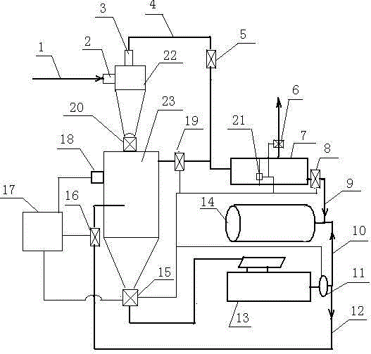
[0032] Such as figure 1 , one A fracturing fluid recovery anti-erosion sand removal system is characterized in that it includes at least one cyclone desander 22, and the desander fluid inlet 2 of the cyclone desander 22 is connected with a sand-containing fluid pipeline 1, so The gas-liquid outlet 3 at the top of the cyclone desander 22 is connected to a gas-liquid separator 7 through the gas-liquid pipeline 4, and the bottom outlet of the cyclone desander 22 is connected to a sand storage tank 23 through the cyclone sand discharge remote control valve 20 ;

[0033] The gas outlet of the gas-liquid separator 7 is provided with a natural gas outlet needle valve 6, and the liquid outlet of the gas-liquid separator 7 is connected to a fracturing fluid recovery tank 14 through the separator drain line 9;

[0034] The upper part of the sand storage tank 23 is connected to the inlet of the gas-liquid separator 7 through the pressure release switch 19, and the sand outlet at the bot...

Embodiment 2

[0040] On the basis of Example 1, the gas-liquid pipeline 4 is provided with a high-pressure needle valve 5, and the working pressure of the cyclone desander 22 is 35MPa; separation flow rate: liquid 1.5 cubic meters / min; gas 5×10 4 square / day; separation particle size: 20um; the rated pressure of the sand storage cylinder 23 is 35MPa. During the working process, open the wellhead tubing valve, close the high-pressure needle valve 5 at the same time, open the cyclone sand discharge remote control valve 20, and close the sand storage cylinder sand discharge remote control valve 15 through the PLC controller 17, and observe the inside of the well. The liquid flow rate of the flowback liquid entering the cyclone desander 22; when the liquid flow rate of the flowback liquid entering the cyclone desander 22 in the well is ≤ 1 cubic meter per minute, open the high-pressure needle valve 5 and pass through the cyclone desander 22. The gas-liquid mixture of the flowback liquid processe...

Embodiment 3

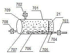
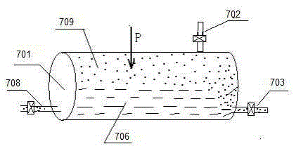
[0042] On the basis of embodiment 1 or 2, at present as image 3 The volumetric gas-liquid separator shown must be separated under a certain pressure condition, otherwise, the volume of the gas under normal pressure is too large, and the gas-liquid flow rate is too fast, and the gas-liquid flow rate cannot be reached in a volumetric separator of a certain volume. The gravity separation condition of the liquid; when the volumetric separator adopts a certain pressure for separation, the volume of the gas will shrink, which can greatly reduce the velocity of the fluid in the separator; if the pressure in the separator reaches 5MPa, the volume of the gas It is 1 / 50 of the normal pressure, and the flow rate of the fluid in the separator can also be changed in the range of 50 times less than the volume of the normal pressure according to the gas-liquid ratio, so as to achieve a better effect of gas-liquid separation;

[0043] But when there is pressure in the separator, when the sep...


PUM

PropertyMeasurementUnit
volumeaaaaaaaaaa

Abstract

The invention relates to a fracturing fluid recovery erosion-prevention sand-removal system and method. The system at least comprises a cyclone sand remover, a gas-liquid separator and a sand storage tube, wherein a gas outlet of the gas-liquid separator is provided with a natural gas outlet needle valve; a liquid outlet of the gas-liquid separator is communicated and connected with a fracturing fluid recovery tank; the upper part of the sand storage tube is connected with an inlet of the gas-liquid separator; a sand outlet of the sand storage tube is provided with a sand storage tube sand discharge remote control valve; an outlet of the sand storage tube sand discharge remote control valve is connected with a vibration sieve; an outlet of a liquid storage tank of the vibration sieve is provided with a remote control liquid discharge pump; an outlet of the remote control liquid discharge pump is divided into two branches; one branch is connected with the fracturing fluid recovery tank; the other branch is connected with a liquid inlet formed in the middle part of the sand storage tube; the system also comprises a PLC (programmable logic controller); the PLC is respectively and electrically connected with an ultrasonic wave detector, a sand-containing fluid flushing remote control value, a gas separator liquid level meter, a remote control high-pressure valve, a pressure release switch and the sand storage tube sand discharge remote control valve. The erosion of blasting sand-containing fluid on a ground pipe manifold is relieved.

Description

technical field [0001] The invention relates to the field of recovery of fracturing fluid in the field of exploration and development of oil and gas fields, in particular to a system and method for recovery of fracturing fluid, anti-erosion and sand removal. Background technique [0002] The fracturing operation is to transform the oil and gas layers, improve the conductivity, and make the oil and gas layers meet the development conditions. It is a technological measure to increase the production of oil and gas fields. Basically, every well needs to be fracturing; The development of fracturing technology requires a large amount of surface water; because a large number of additives and high-strength proppant are added to the fracturing fluid, the liquid discharged from the well after fracturing must be recycled and reused, otherwise, when it is discharged in When it is on the ground, it will pollute surface water and the environment. Whether it is the discharge of fracturing...

Claims


Application Information

Patent Timeline
Patent Type & Authority Applications(China)
IPC IPC(8): C09K8/62B01D21/26B01D19/00
CPCB01D19/00B01D21/267C09K8/62
Inventor 孙虎李尊团邓继学王祖文白明伟米虎宁樊启国徐迎新张晓祥韩静静景志明韩蓉龙庆陈卫东
Owner BC P INC CHINA NAT PETROLEUM CORP
Learn More