

Mechanical grate-type garbage single-furnace gasifying incineration and boiler system
A mechanical grate and incinerator technology, applied in incinerators, combustion methods, combustion types, etc., can solve the problem that the heat energy recovery system and the flue gas treatment system have great influence, cannot realize continuous gasification and incineration of waste, and reduce heat conversion. Efficiency and other issues, to achieve the effect of ensuring the rate of ash on ignition, improving heat exchange efficiency, and reducing heat loss
- Summary
- Abstract
- Description
- Claims
- Application Information
AI Technical Summary
Problems solved by technology
Method used
Image

Examples
Embodiment Construction
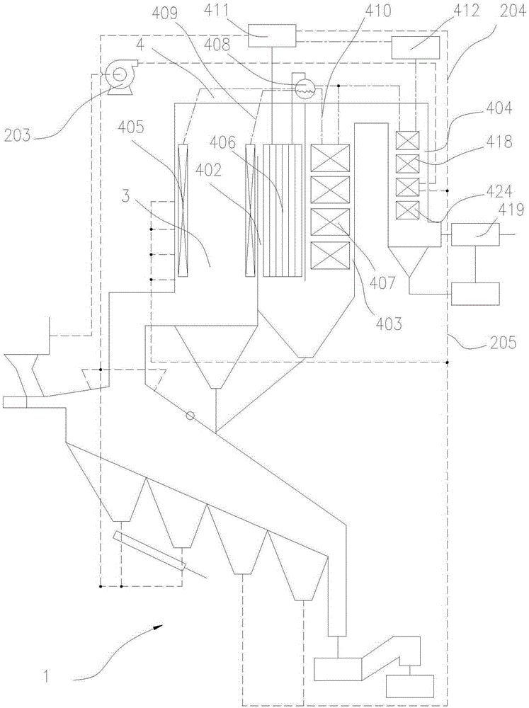
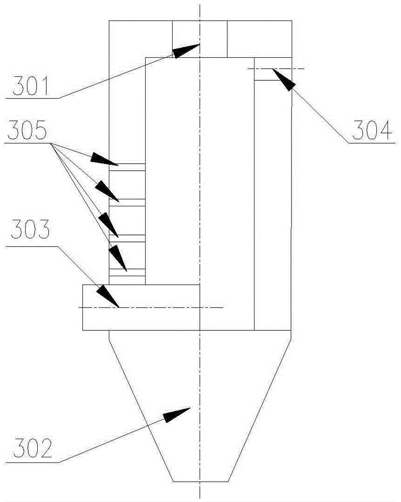
[0041] see figure 1 , is a preferred embodiment of mechanical grate type garbage single furnace gasification incineration and its boiler system, including gasification incinerator 1, cyclone combustion chamber 3, air supply system 2,
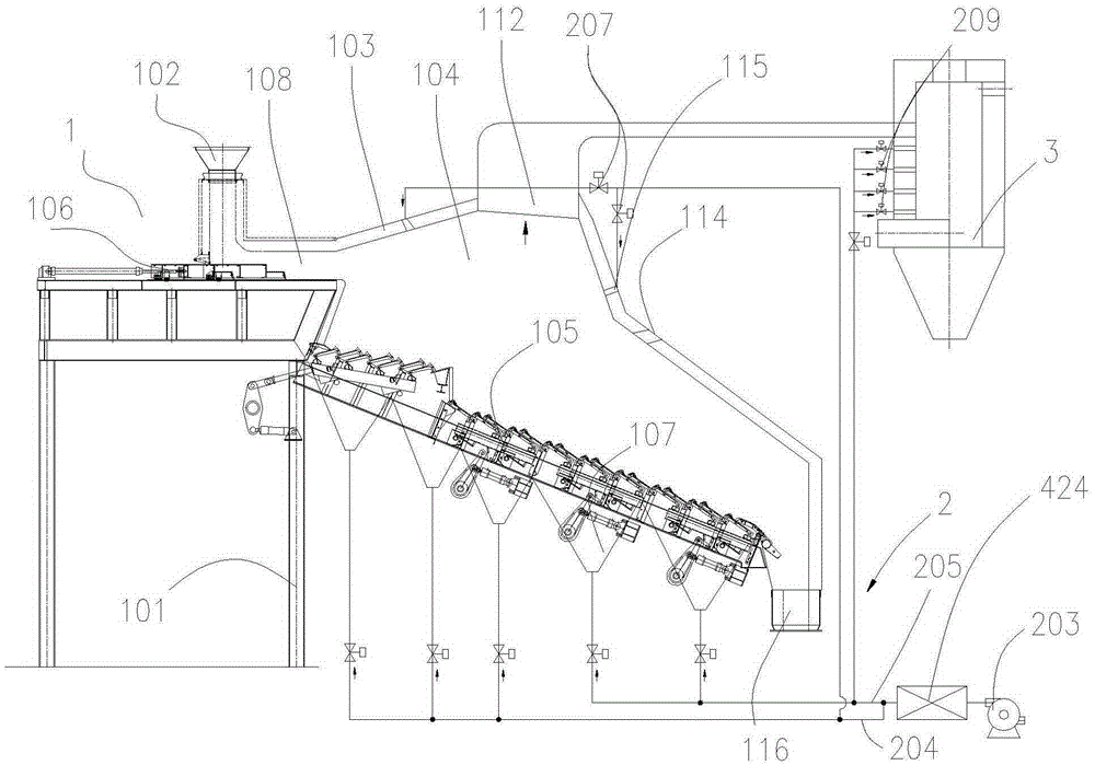
[0042] see figure 2 , the gasification incinerator 1 includes a furnace rack 101, and a feed bin 102, a furnace body, and a slag outlet 116 arranged in sequence along the feeding direction on the furnace rack 101, and the furnace body includes a furnace shell 103, a movable furnace Bed 105, the mobile hearth 105 adopts a mechanical grate type mobile hearth 105 independently driven in sections, and the grate of the mechanical grate type mobile hearth 105 is composed of movable grate plates and fixed fire grate plates. Arranged together, adjacent groups of movable grate plates are connected by tie rods and driven by a set of driving devices. The mechanical grate type moving hearth 105 is used as a carrier for transporting garbage, and its imple...
PUM
 Abstract
Description
Claims
Application Information