

Composite material device
A technology of composite materials and devices, applied in metal material coating technology, thin material treatment, electrolytic coating, etc., can solve the problems of poor repeatability, low energy conversion efficiency, high production cost, etc., and achieve low cost, easy preparation, and environmental protection friendly effect
- Summary
- Abstract
- Description
- Claims
- Application Information
AI Technical Summary
Problems solved by technology
Method used
Image

Examples
Embodiment 1
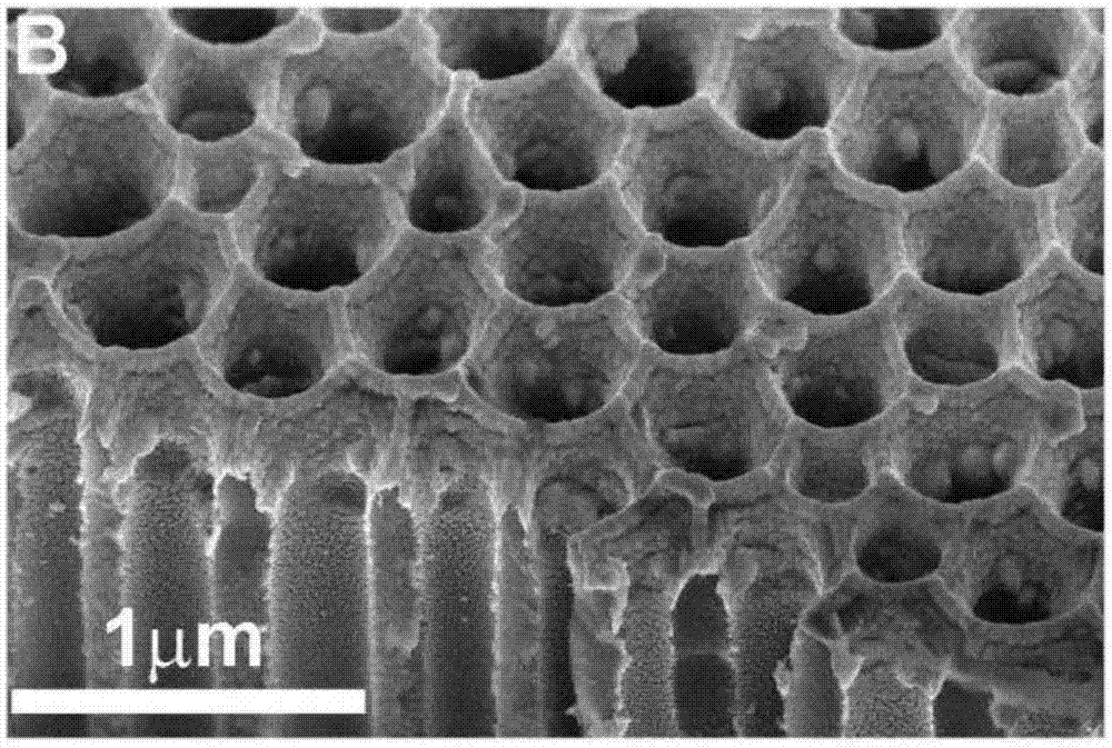
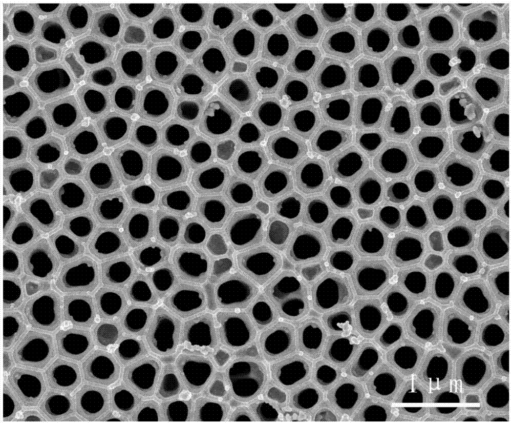
[0136] Step 1: Prepare a porous alumina template (hereinafter referred to as NPT) by using a two-step anodic oxidation method. The preparation method includes: placing the aluminum foil in 0.3M phosphoric acid at 5°C for anodic oxidation, the oxidation voltage starts from 50V, increases by 10V every 2 minutes until 150V, and then maintains for 24 hours to complete the first oxidation. Then the aluminum oxide film formed by the first oxidation is dissolved, and the second oxidation is carried out under the same conditions as the first oxidation. After the second oxidation, after the second oxidation, put the aluminum foil with the porous aluminum oxide film into the mixed solution containing 1MCuCl2 and 0.1M HCl to dissolve the aluminum substrate. Finally, the porous alumina thin film membrane was moved into 5 wt% H 3 PO 4 , the hole was expanded at 30° C. for about 1 hour to obtain the NPT of Example 1.
[0137] figure 1 is a scanning electron micrograph of Au / NPT. The th...
Embodiment 2
[0147] (1) According to the method of Example 1, NPT was obtained.
[0148] (2) Deposit gold (Au) on the disordered surface of the above-mentioned NPT and the inner wall of the hole on the surface using an ion beam coating instrument GatanModel682. Specifically, the deposition vacuum is 5×10 -4 Pa, the electron gun voltage is 7Kev, the current is 300uA, and the deposition time is 16min. The obtained product is the composite material device of Example 2 (hereinafter referred to as Au / D-NPT).
[0149] The Au / D-NPT includes NPT and gold particles attached to the inner walls of the pores of the NPT, and the gold particles are distributed in the range of 0-2 microns from the surface to the inside of the disordered surface of the NPT. The Au / D-NPT may also include a gold layer covering the disordered surface of the NPT. The gold layer may only cover the region without pores on the disordered surface. The thickness of the gold layer is about 60-90 nanometers. The thickness of Au / D...
Embodiment 3
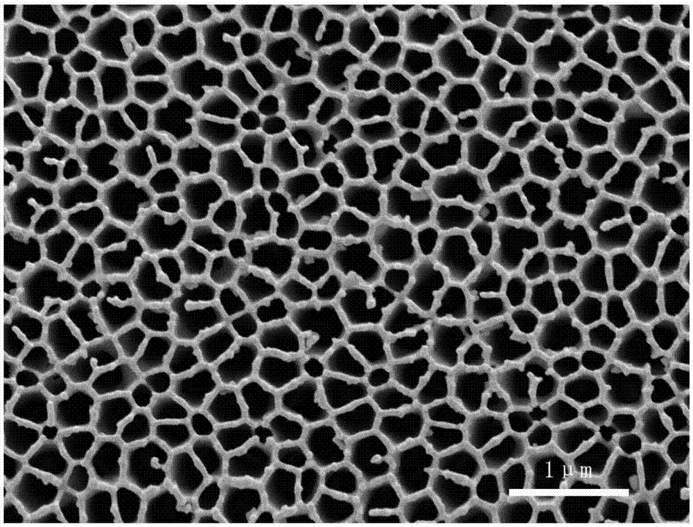
[0170] Step 1: The method of preparing NPT with an average pore diameter of about 200nm is as follows:
[0171]A porous alumina template (hereinafter referred to as NPT) was prepared by a two-step anodic oxidation method. The preparation method includes: placing the aluminum foil in 0.5M phosphoric acid at 5°C for anodic oxidation, the oxidation voltage starts from 50V, increases by 10V every 2 minutes until 150V, and then maintains for 24 hours to complete the first oxidation. Then the aluminum oxide film formed by the first oxidation is dissolved, and the second oxidation is carried out under the same conditions as the first oxidation. After the second oxidation, after the second oxidation, put the aluminum foil with the porous aluminum oxide film into the mixed solution of 1MCuCl2 and 0.1M HCl to dissolve the aluminum substrate. Finally, the porous alumina thin film membrane was moved into 5 wt% H 3 PO 4 , the hole was expanded at 30° C. for about 1 hour to obtain the NP...
PUM
| Property | Measurement | Unit |
|---|---|---|
| particle diameter | aaaaa | aaaaa |
| particle diameter | aaaaa | aaaaa |
| particle diameter | aaaaa | aaaaa |
Abstract
Description
Claims
Application Information