Electrotyping forming method of waveguide assembly

A component and waveguide technology, which is applied in the field of electroforming of waveguide components, can solve the problems of poor toughness and brittle electroformed layer, and achieve the effects of easy processing, fine crystallization and good toughness

Inactive Publication Date: 2016-04-06
HUNAN AEROSPACE HUNAYU COMM TECH CO LTD
View PDF1 Cites 8 Cited by
  • Summary
  • Abstract
  • Description
  • Claims
  • Application Information

AI Technical Summary

Problems solved by technology

[0003] The invention provides an electroforming method for waveguide components to solve the technical problems that the ele

Method used


Image

  • Electrotyping forming method of waveguide assembly
  • Electrotyping forming method of waveguide assembly
  • Electrotyping forming method of waveguide assembly

Examples


Embodiment 1

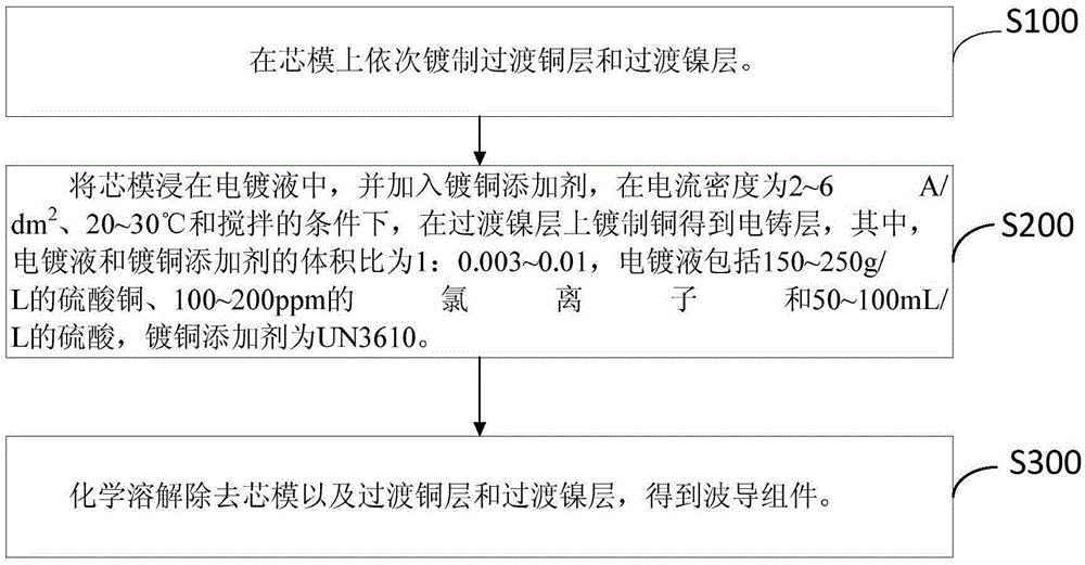
[0049] A transition copper layer and a transition nickel layer are sequentially plated on the aluminum mandrel.

[0050] Immerse the mandrel in the electroplating solution and add copper plating additives at a current density of 2A / dm 2 , 20° C., and a stirring speed of 20 rpm, electroplating on the transition nickel layer for 96 hours, and plating copper to obtain an electroformed layer. Wherein the volume ratio of the electroplating solution and the copper plating additive is 1:0.003, the electroplating solution includes 150g / L of copper sulfate, 100ppm of sodium chloride and 50mL / L of sulfuric acid, the copper plating additive is UN3610, and the current density gradually increases during the plating process. Increase, the current density of high frequency pulse power supply is 2~6A / dm 2 , the duty cycle is 60~90, the negative current density is 2~6A / dm 2 .

[0051] Soak the mandrel provided with the electroformed layer in 50 g / L sodium hydroxide solution at 60° C. until ...

Embodiment 2

[0055] A transition copper layer, a transition nickel layer and a gold layer are sequentially plated on the aluminum mandrel.

[0056] Immerse the mandrel in the electroplating solution and add copper plating additives at a current density of 4A / dm 2 , 25° C., and a stirring speed of 50 rpm, electroplating was performed on the gold layer for 96 hours, and copper was plated to obtain an electroformed layer. Wherein the volume ratio of the electroplating solution and the copper plating additive is 1:0.06, the electroplating solution includes copper sulfate of 180g / L, potassium chloride of 80ppm and sulfuric acid of 70mL / L, the copper plating additive is UN3610, and the current density gradually increases during the plating process. Increase, the current density of high frequency pulse power supply is 2~6A / dm 2 , the duty cycle is 60~90, the negative current density is 2~6A / dm 2 .

[0057] Soak the mandrel provided with the electroformed layer in 70g / L sodium hydroxide solutio...

Embodiment 3

[0061] A transition copper layer, a transition nickel layer and a silver layer are sequentially plated on the aluminum mandrel.

[0062] Immerse the mandrel in the electroplating solution and add copper plating additives at a current density of 6A / dm 2 , 30° C., and a stirring speed of 50 rpm, electroplating was performed on the silver layer for 96 hours, and copper was plated to obtain an electroformed layer. Wherein the volume ratio of electroplating solution and copper plating additive is 1:0.01, and electroplating solution includes the copper sulfate of 250g / L, the sodium chloride of 200ppm and the sulfuric acid of 100mL / L, and copper plating additive is UN3610, and current density gradually Increase, the current density of high frequency pulse power supply is 2~6A / dm 2 , the duty cycle is 60~90, the negative current density is 0.5~2A / dm 2 .

[0063] Soak the mandrel provided with the electroformed layer in 80g / L sodium hydroxide solution at 70°C until no air bubbles ar...


PUM

PropertyMeasurementUnit
Current densityaaaaaaaaaa
Cross-sectional areaaaaaaaaaaa

Abstract

The invention discloses an electrotyping forming method of a waveguide assembly. The electrotyping forming method includes the following steps that a transition copper layer and a transition nickel layer are sequentially manufactured on a mandrel in a plating manner; the mandrel is soaked in a plating solution, a copper plating additive is added, copper is manufactured on the transition nickel layer in a plating manner obtain an electroformed layer under the stirring condition that the current density is 2-6 A/dm<2> and the temperature is 20-30 DEG C, wherein the size ratio of the plating solution to the copper plating additive is 1:(0.003-0.01), the plating solution comprises copper sulfate of 150-250 g/L, chloride ions of 100-200 ppm, and sulfuric acid of 50-100 mL/L, and UN3610 serves as the copper plating additive; and the mandrel, the transition copper layer and the transition nickel layer are removed through chemical dissolution, and the waveguide assembly is obtained. By means of the electrotyping forming method of the waveguide assembly, the electroformed layer which is fine in crystallization, compact in texture and good in tenacity can be obtained by selecting the appropriate plating solution, the appropriate copper plating additive and the appropriate copper plating condition, machining of the waveguide assembly is facilitated, and the rate of qualified products is increased.

Description

technical field [0001] The invention relates to the field of preparation of waveguide components, in particular to an electroforming method for waveguide components. Background technique [0002] The waveguide component is a key component in the radar feeder system, which is responsible for transmitting the high-power microwave signal of the transmitter. With the continuous improvement of microwave frequency, the requirements for the dimensional accuracy of waveguide components are also extremely strict, and traditional machining methods can no longer meet the requirements for the use of ultra-high frequency waveguide components. The electroforming method of waveguide components has high dimensional accuracy, but the resulting electroformed layer is brittle and has poor toughness. The waveguide components formed after electroforming generally need to be processed by turning, milling, drilling, etc. Among them, the waveguide components are prone to cracking and directly form...

Claims


Application Information

Patent Timeline
IPC IPC(8): C25D1/00C25D1/10C25D1/22C25D3/38C25D5/18C25D5/12
CPCC25D1/00C25D1/10C25D3/38C25D5/12C25D5/18
Inventor 司崇岭欧长雄郭春林黄佐军
Owner HUNAN AEROSPACE HUNAYU COMM TECH CO LTD
Why Eureka
Try Eureka